A Free Body Diagram (FBD) is a simplified graphical representation used in physics to show all the forces acting on a body at a particular instant. It helps in analyzing the motion or equilibrium of an object by clearly identifying the magnitude and direction of each force acting on it.
In mechanics, drawing a free body diagram is considered the first and most crucial step before applying Newton’s laws of motion. By isolating the object from its surroundings and representing only the forces acting on it, an FBD allows us to calculate the net force and predict how the body will behave under those forces.
A free body diagram is a symbolic and diagrammatic representation of an object (either a complete body or a part of a system) in which all external forces are shown using directed arrows. The diagram does not represent motion directly but provides the foundation to determine motion mathematically.
Features of a Free Body Diagram
A properly drawn free body diagram has the following characteristics:
All external forces acting on the body are shown.
Forces are represented by arrows, where:
The direction of the arrow indicates the direction of the force.
The length of the arrow represents the relative magnitude of the force.
Moments or torques, if present, are shown using curved arrows.
The diagram is drawn with respect to a well-defined coordinate system.
Only the selected body is shown; the surroundings are replaced by the forces they exert.
While drawing an FBD, certain assumptions are made based on the problem statement. Forces like air resistance or drag are usually neglected unless explicitly mentioned.
Components of a Free Body Diagram
Typically, a free body diagram consists of:
A simplified sketch of the body (often represented as a point or box)
A coordinate axis for resolving forces
Force vectors acting on the body
Moment vectors, if rotational effects are involved
Exclusions in a Free Body Diagram
A free body diagram does not include:
Other bodies present in the system
Constraints such as supports or strings (only the forces due to them)
Internal forces within the body
Significance of Free Body Diagram
Free body diagrams play a vital role in mechanics due to the following reasons:
They help in clearly understanding the nature and direction of forces
They assist in predicting the motion or equilibrium of a body
They make it easier to apply mathematical equations correctly
They help in identifying the most effective point and direction for applying a force to produce desired motion
How to Make Free Body Diagram
Follow the steps mentioned below to make Free Body Diagram.
Step 1: Mark Object Boundary: First of all identify the body for which the analysis has to take place, draw the boundary of the object.
Step 2: Identify Contact Surfaces: Once the body is identified and boundary is clear, we need to identify the contact surfaces of the body (any surface which body touches is the contact surface for the body), which can be identified by drawing a dot on the object boundary, when any surface touches the body. When there is a dot it is for sure that there is a contact force.
Identifying Contact surface
Step 3: Define a Coordinate System: Define a coordinate system and label clearly specify positive directions.
Defining coordinate system
Step 4: Identify Contact Forces: For every dot define the contact force acting at that dot with an arrow pointing away from the dot, (since the force is acting on the body it will always be away from the surface and towards the body) and label this forces.
Step 5: Draw other forces acting on the body such as Weight of the body, electric or magnetic force in case it also exists.
Drawing forces acting on the body
Step 6: In case the body have any resulting acceleration show that using an acceleration vector.
Showing acceleration acting on the body
Free Body Diagram in Physics
Free Body Diagram in physics can be made for several physical phenomena such as a body in motion is subjected to some load. In this section we will discuss FBD for following types
Free Body Diagram of Circular Motion
Free Body Diagram of Frictional Force
Free Body Diagram of Friction on Inclined Plane
1. Free Body Diagram of Circular Motion
Consider a ball initially at the bottom of a circular path, let's use try to understand the Free Body Diagram of the when it move on the circular path with a velocity of v. In this section we will learn how the different forces are acting on different positions of the ball in the circular path.
A). Free Body Diagram of the Ball at Rest
When the ball will be at rest it will have a its weight acting downwards (W = mg), which will cause a Normal Force (N) from the surface to act on the object.
FBD of the ball at rest
B). Free Body Diagram of Ball at the Bottom of the Path when moving with a velocity of v:
We know every object moving on a circular path with a velocity v of a circular path experiences a Centrifugal Force away from the center. So when the ball will start moving it will experience Centrifugal Force given as
Cf = mv2/r
where,
m is the mass of the ball,
v is the velocity with which the ball is moving and,
r is the radius of the circular path,
Hence the free body diagram will look like as follows:
FBD of moving ball at bottom
C). Free Body Diagram of the Ball at the Middle of the Path when Moving with a Velocity of v:
We know every object moving on a circular path with a velocity v of a circular path experiences a Centrifugal Force away from the center, so when the ball will start moving and reach the horizontal position as shown, it will experience a forces (Centrifugal Force Cf = mv2 / r) , which will cause a Normal Force(N) to come into action towards the center and weight will always be acting vertically downwards.
Hence the free body diagram will look like:
FBD of moving ball in middle
D). Free Body Diagram of the ball at the Topmost Position of the path when moving with a velocity of v:
When the ball will reach the highest position of the circular path, it will have its weight (W = mg) acting downwards, and Centrifugal Force (Cf = mv2 / r), which will cause a Normal Force (N) to act towards the center of the path.
Hence the Free Body Diagram can be shown as:
FBD of moving ball at top
2. Free Body Diagram for Frictional Force
When a body is placed on a plane, instantaneously its Weight (W=mg) will start acting vertically downwards which will cause a Normal Force (N) from the ground to come into action. Now when the body is at rest the friction action of the body will be zero, but as soon as the body starts moving a friction (f = μN) will start acting opposite to the direction of motion.
Hence the Free Body Diagram of block placed on plane with coefficient of friction (μ), will look like as shown below where, 0 \leq f \leqslant \mu N, is applicable
FBD for Frictional force
3. Free Body Diagram of Inclined Friction
Consider a body of mass m placed on an inclined plane, it weight will start acting vertically downwards, but friction and Normal Forces will act along and perpendicular to the inclined surface, so will consider a coordinate system where x axis is parallel to the inclined surface and y-axis is perpendicular to it.
FBD of Inclined Friction
Since inclined angle is making a θ angle with the horizontal, the component of weight parallel to inclined will make a 90 - θ angle with the vertical, hence the components of weight can be resolved as Wp = mgcosθ and W|| = mgsinθ. See the figure:
Free Body Diagram of Inclined Friction with Co-ordinate system
After, Resolution of Weight Component along perpendicular and parallel to the inclined plane is shown below:
FBD of Inclined Friction after Resolution
Now the normal force (N) will start acting perpendicular to the surface of the inclined and a friction (f = μN) will act parallel to the surface of the inclined. Hence the free body diagram will look like:
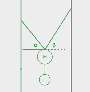
Example 1: Draw the Free Body Diagram of mass M, as given below.
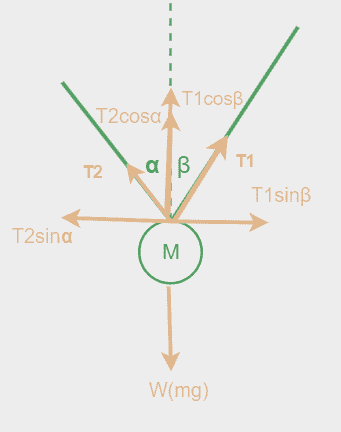
Solution: Consider the Block A: When the mass M, is suspended using the two ropes, it weight(Mg) will start acting downward, which will cause tension in the ropes, let use name this tensions in the ropes as T1 and T2, then we can have our initial FBD as shown below:
Now, the tension in the strings will act such that, it will try to balance the weight of the ball (Mg), so we can resolve the tension T1 and T2, in there corresponding vertical and horizontal component.
Resolution of T1: Since T1 is at an angle β with the vertical, therefore the component of T1 along the vertical will become, T1cosβ and the component along the horizontal will become T1sinβ.
Resolution of T2: Since T1 is at an angle α with the vertical, therefore the component of T2 along the vertical will become, T2cosα and the component along the horizontal will become T2sinα.
Hence, we can draw the final FBD, will all the forces resolved along the vertical and horizontal components only, as below:
Example 2: A block is at rest on a platform with coefficient of friction μ is pulled by a force F acting at an angle θ, with the horizontal as show draw the free body diagram of the block.
Solution: When the block is placed on the platform, its weight (Mg) will starting acting vertically downwards.
The weight acting downwards on the body will cause a normal force (F) from platform to act in the vertically upward direct.
Now when the force F will come into picture, since it is inclined at and angle θ, with the horizontal it will have to components one along the horizontal (Fcosθ) and the other along the vertical (Fsinθ)
Since there is no other force in the horizontal force in the horizontal direction other than Fcosθ, this will try to move to body on the platform which will cause the friction to act in the direction opposite to the direction of motion, hence the FBD of the body will look like:
Unsolved Questions
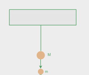
Question 1: Draw the Free Body Diagram of mass M and m, when they are suspended as shown in the figure given below.
Question 2: Draw the Free Body Diagram for the string ball system when they are arranged as shown below:
Question 3: Draw the free body diagram for block A and block B shown in the figure.


.png)


.png)

.png)
-660.png)
.png)
-660.png)