Electrical resistance is the property of a material that opposes or restricts the flow of electric current through it. It measures how strongly a material resists the movement of electric charges in a conductor. Materials with low resistance allow current to flow easily (conductors), while materials with high resistance strongly oppose the flow of current (insulators). It is represented by R, and its SI unit is the ohm (Ω).
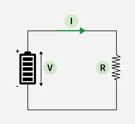
Georg Simon Ohm was a German physicist who gave a law which is known as Ohm's law. According to Ohm’s Law, the current flowing through a conductor is directly proportional to the potential difference across it, provided temperature and other physical conditions remain constant
V \propto I
\boxed{ V = I \times R}
Resistance dimensional formula = M¹L²T⁻³A⁻²
Formula for Resistance
where
- R= Resistance of the material
- A = Cross Sectional Area
- L = Lenght of the Wire
- 𝞺 = Resistivity
Factors Affecting Electrical Resistance
1. Material of the Conductor
As resistance is the physical property of a material, different materials can have different values of resistance. As conductors have less resistance compared to semiconductors and insulators, and semiconductors have more resistance than conductors but less than insulators.
2. Length of the Conductor
By the relation between resistance and resistivity, we know that the length of the conductor and the resistance of the conductor are directly proportional to each other, i.e., the longer the length of the wire, the more resistance it will offer in the circuit.
3. Cross-Sectional Area of the Conductor
As the relation between Specific Resistance or resistivity and Resistance is given by R = (ρ×L)/A. In which we can see that the resistance R of the conductor and the cross-sectional area A of the conductor are inversely proportional to each other, i.e., if one increases, the other should decrease if all other things remain constant. Thus, by increasing cross sectional area of the conductor, the resistance of it decreases.
4. Temperature of the Conductor
As temperature increases, the resistance of a conductor generally increases due to increased collision between electrons and atoms.
Electrical Resistor Symbol
Although every material offers some resistance to the flow of charges, there are specific electrical devices that are used in circuits to provide the desired electrical resistance. These are called electrical resistors. The symbols of electrical resistors are given below:

Resistivity
Resistivity is a fundamental property of a material that indicates how strongly it opposes the flow of electric current. Materials with low resistivity allow current to flow easily, while materials with high resistivity strongly resist the flow of current. Resistivity can be defined as the resistance of a material of unit length and unit cross-sectional area.
It can also be expressed as the ratio of electric field to current density:
\rho = \frac{E}{J} where,
- ρ is the resistivity of the material and is measured in Ω.m
- E is the electric field and is measured in V · m-1
- J is the current density and is measured in A · m-2
Units of Resistivity
- Resistivity is commonly represented by the Greek letter ρ (rho).
- SI unit of electrical resistivity is the Ohm-meter (Ω-m)
Relation between Resistance and Resistivity
Mathematically formula for resistivity or the relation between resistance and resistivity is given as follows:
\rho = \frac{RA}{L}
R = \frac{\rho L}{A} Where,
- R is the Resistance,
- L is the Length and
- A is the cross-sectional area of the conductor.
Resistivity of Some Common Materials
Materials with a low value of resistivity conduct electricity very well, and insulators have a higher value of resistivity than conductors. Some materials and their standard specific resistance (Resistivity) at 20°C:
Material | Resistivity (in Ω-m) |
|---|---|
| Aluminum | 2.8 × 10⁻⁸ |
| Copper | 1.7 × 10⁻⁸ |
| Gold | 2.4 × 10⁻⁸ |
| Carbon (Graphite) | 1 × 10⁻⁵ |
| Germanium | 4.6 × 10⁻¹ |
| Iron | 1.0 × 10⁻⁷ |
| Lead | 1.9 × 10⁻⁷ |
| Nichrome | 1.1 × 10⁻⁶ |
| Silver | 1.6 × 10⁻⁸ |
Difference Between Resistance And Resistivity
The difference between resistance and resistivity is discussed in the table below.
| Resistance | Resistivity | |
|---|---|---|
| Definition | The property of the material that opposes the flow of the electric current in any material is called the resistance of that material. | Resistivity is the resistance of a conductor of unit length and unit cross-sectional area. |
| Symbol | It is denoted by the symbol R | It is denoted by the symbol ρ |
| Formula | The formula for the resistance is, R = V/I | The formula for the resistivity is,
|
| SI unit | The SI unit of resistance is the ohm (Ω) | The SI unit of resistivity is Ohm-m(Ω-m) |
Related Articles:
Sample Problems
Question 1: What is the resistance of the circuit in which the applied voltage is 12 V, and the current flowing through it is 4 A?
Solution: Given,
V = 12 V
I = 4 A
According to the relation
R = V/I
Therefore,
R = 12 V/4 A
R = 3 Ω
Thus, the electrical resistance of the circuit is 3 Ω
Question 2: What is the current flowing through the circuit in which the applied voltage is 12 V, and the resistance of the conductor is 3 ohms?
Solution: Given:
V = 12 V
R = 3 Ω
According to the relation, V = IR
⇒ I = V/R
I = 12 V/3 Ω
I = 4 A
Thus, the current flowing through the circuit is 4 A.
Question 3: What is the voltage applied to the circuit in which the current passing through the conductor is 4 A and the resistance of the conductor is 3 Ω?
Solution: Given:
I = 4 A
R = 3 Ω
According to the relation
V = IR
V = 4 A × 3 Ω
V = 12 V
Thus, the voltage across the circuit is 12 V.
Question 4: Calculate the resistance of a copper wire of length 4 m and the area of cross-section 10-6 m2. The resistivity of copper is 1.7 × 10⁻⁸ Ωm.
Solution: Using a formula,
R = (ρ×L)/A
R = (1.7 x 10⁻⁸ Ωm) × 4 m/10-6 m2
R = 6.8×10⁻² Ω
The resistance of the copper wire is 6.8×10⁻² Ω
Question 5: A copper wire of length 4 m and area of cross-section 10-6 m2 has a resistance of 6.8 × 10⁻² ohms. Calculate the resistivity of copper.
Solution: Using the formula
ρ = (R×A)/L
ρ = (6.8 × 10-2) × 10-6 / 4
ρ = 1.7 × 10⁻⁸ Ωm.
Thus, the resistivity of the copper wire is 1.7 × 10⁻⁸ Ωm.