A combination of resistors refers to the connection of two or more resistors in a circuit in such a way, either in series, parallel, or a combination of both, which collectively provides a specific total resistance, helps control the flow of current, and distributes voltage appropriately across different parts of the circuit for the proper functioning of electrical devices.
1. Series Combination
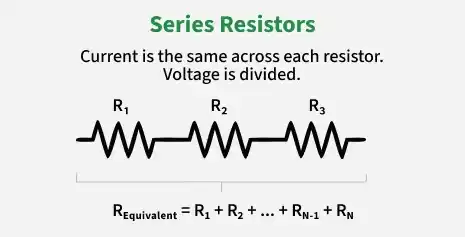
When two or more resistors are connected one after another in a single path such that the current has only one path to flow, the arrangement is known as a series combination of resistors. In this type of connection, the same current flows through each resistor because charge leaving one resistor directly enters the next without any branching. This makes the current identical at every point in the circuit.
If a potential difference V is applied across the combination, it gets distributed among the resistors. Let the potential difference across R1 be V1 and across R2 be V2. According to Ohm’s law, the voltage across each resistor is given by:
The total potential difference across the series combination is equal to the sum of individual potential differences:
Substituting the values:
From this, the equivalent resistance of the series combination can be derived as:
If there are more than two resistors, say R1,R2,R3,…,Rn connected in series, then the equivalent resistance becomes:
This shows that in a series combination, the total resistance is simply the sum of all individual resistances. As a result, the equivalent resistance is always greater than the largest individual resistance in the circuit. This property is important in controlling current in electrical devices, as increasing resistance reduces the overall current flow in the circuit.
2. Parallel Combination
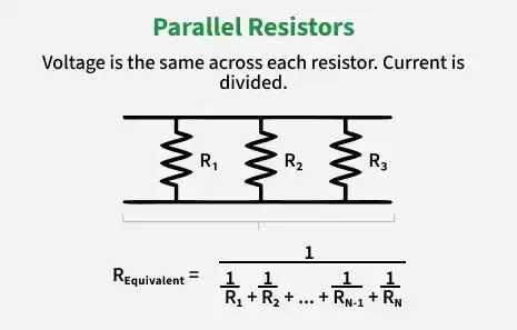
When two or more resistors are connected between the same two points such that there are multiple paths for current to flow, the arrangement is called a parallel combination of resistors. In this type of connection, the potential difference across each resistor remains the same, while the total current gets divided among different branches. The current entering the junction splits into different parts, say I1 and I2, flowing through R1 and R2 respectively, and the total current is given by I = I1 + I2
Applying Ohm’s law to each branch, the potential difference across both resistors is the same, so
Rewriting the currents, we get
Therefore, total current becomes
If the combination is replaced by an equivalent resistance Rp, then according to Ohm’s law
For n resistors connected in parallel, the equivalent resistance is:
Thus, in a parallel combination, the equivalent resistance is always smaller than the smallest individual resistance, which means adding more resistors decreases the overall resistance of the circuit.
Power Dissipation in Resistors
Electrical energy converts into heat in resistors.
Power dissipated:
Using Ohm’s law:
and
This is called Joule heating.
Heating Effect in Series and Parallel Circuits
a. Series Combination: Since same current flows: larger resistance dissipates more power.
P\propto R
b. Parallel Combination: Since same voltage acts: smaller resistance dissipates more power.
P\propto \frac1R
Internal Resistance and External Resistance
Every source possesses:
- internal resistance,
- external load resistance.
Total circuit resistance becomes:
Current is therefore:
Solved Problems
Problem 1: How much current will an electric lamp draw from a 220 V source, if the resistance of the lamp is 1000 Ω?
Solution: Given that,
The source voltage, V, is 220 V.
The resistance of the lamp, R, is 1000 Ω.
The formula to calculate the current drawn is:
I = V / R
Substitute the given values in the above expression as:
I = 220 V / 1000 Ω
= 0.22 A
Hence, the current drawn through the electric lamp is equal to 0.22 A.
Problem 2: If the resistance of the bulb filament is 200 Ω, how much current will an electric bulb draw from a 220 V source?
Solution: Given that,
The source voltage, V, is 220 V.
The resistance of the bulb, R, is 200 Ω.
The formula to calculate the current drawn is:
I = V / R
Substitute the given values in the above expression as:
I = 220 V / 200 Ω
= 1.1 A
Hence, the current drawn through the electric bulb is equal to 1.1 A.
Problem 3: The potential difference between the terminals of an electric bulb is 30 V when it draws a current of 6A from the source. What current will the bulb draw if the potential difference is increased to 120 V?
Solution: Given that,
The potential difference across the electric bulb, V, is 30 V.
The current drawn, I is 6 A.
The increased potential difference, V, is 120 V.
According to Ohm’s law, the formula to calculate the resistance is:
R = V / I
= 30 V / 6 A
= 5 Ω
When the potential difference is increased to 120 V, the current drawn is:
I' = V / R'
Substitute the given values in the above expression as:
I' = 120 V / 5 Ω
= 24 A
Hence, the current drawn through the electric bulb is equal to 24 A.
Problem 4: A wire has a resistance of 4 Ω of some given material with length l and cross-sectional area of A. How much will be the resistance of another wire with the same material, having length l/2 and cross-sectional area of 2A?
Solution: Consider the resistance of the first wire as:
R1 = ρl / A
where ρ is the resistivity, l is the length, and A is the cross-sectional area of the first wire.
But it is given that the resistance, R1 is 4 Ω.
Therefore,
4 Ω = ρl / A ......(1)
Now, in case of second wire:
The length of the wire, l2 is l/2 and
The cross-sectional area, A2 is 2A.
Therefore, the resistance for second wire becomes:
R2 = ρl2 / A2
= ρ(l/2) / (2A)
= ρl / 4A
Substitute 4 Ω for ρl / A, from equation (1) in the above expression.
R2 = 4 Ω / 4
= 1 Ω
Hence, the resistance of the second wire is 1 Ω
Unsolved Problems
Question 1: Three resistors 12 Ω, 18 Ω, and 24 Ω are connected in series across 36 V; find total resistance, current, and voltage drop across each resistor
Question 2: Four resistors 6 Ω, 12 Ω, 8 Ω, and 24 Ω are connected in parallel across 48 V; find equivalent resistance and current through each resistor.
Question 3: A lamp draws 3 A when connected to 120 V. If voltage is increased to 240 V, calculate the new current and power consumed.
Question 4: A wire of length 2 m, area 1 mm², and resistance 4 Ω is replaced by another wire of length 3 m and area 0.5 mm² of the same material; find the new resistance.
Question 5: Two resistors 4 Ω and 6 Ω are in series, and this combination is in parallel with an 8 Ω resistor across 24 V; calculate total current drawn and current through each branch.