A High-Level Design (HLD) diagram is a visual representation of a system’s overall architecture and the flow of data between major components. It provides a macro-level view of how different modules, services, and systems interact without going into implementation details.
- Focuses on the big picture by highlighting major system components and their interactions.
- Shows how the system fits within its environment and integrates with external systems.
Importance of High-Level Design Diagrams
High-Level Design (HLD) diagrams are very important since they help in the overall layout of the system. They give a holistic perspective by illustrating how sub-parts combine and how they work. The importance includes:
- Communication: Useful in presenting the design to the stakeholders, developers, and other team members.
- Planning: Helps in planning and scheduling of projects as well as assigning of resources.
- Understanding: This is because it makes it easier to comprehend the more complex architecture of the system under development.
- Documentation: Is useful in the different stages of a project.
- Problem-Solving: Helps the designers detect likely problems during the design stage.
Components of HLD
The main components of high-level design are:
- Modules/Subsystems: Essentially, these are the key aspects of the proposed system that is going to provide elements or modules of the system.
- Interfaces: Interactions that exist between the available modules.
- Data Flow: This is the movement of data products from one module to another as processes are carried out in the model.
- User Interfaces: Looking from perspective of high-level view of user interactions to implement minimum viable features of the user interface.
- External Systems: Communication with other systems that are not part of the implementation or with third parties.
Preparation Required Before Drawing a High-Level Design Diagram
First of all, a number of preparatory steps have to be taken before drawing an HLD diagram in order to avoid mistakes and omissions and produce a truly helpful and informative diagram.
1. Requirements Analysis
In order to get the overall requirements and the extent of the project.
- Gather Requirements: Document requirements from all the stakeholder regarding the business objectives, functional requirement, non-functional requirements and restrictions.
- Analyze Requirements: One has to further decompose and categorize the collected requirements in order to identify what must be delivered by the system and how it is going to be provided.
- Prioritize Requirements: Determine which requirements should be priorities as compared to others and which are mandatory and which are not.
- Document Requirements: Each of the requirements must be recorded systematically, not necessarily in using, but possibly in using the requirement specifications or user stories.
2. Stakeholder Input
To collect information from all the stakeholders to warrant complete compliance with their visions and needs.
- Identify Stakeholders: Discuss all the stakeholders which include project sponsors, the users, developers, testers, and any other interested parties.
- Conduct Meetings: Scheduling with the stakeholders in order to get their opinions and feedbacks for the meetings, workshops or interviews to be conducted.
- Clarify Expectations: Make sure that you have documented the expectations of the other stakeholders. This means its necessary to note their vision, needs among other things or if they have some concerns that they have.
- Maintain Communication: Extend engagement with all the stakeholders to ensure that they continually provide feedback to the project to ensure all the requirements are met.
3. System Context
In order to establish the parameters of the process: Context Diagram: Draw a context diagram that will highlight the relationship that the system has with outside entities (e. g. users, external applications, third parties).
- Define Boundaries: Specifically define what is contained in the system and what is not. It aids in matters concerning scope definition since it is easier to avoid the establishment of large scopes.
- External Interactions: List all data interfaces occur with at least one external system, be it data exchange point, API integration point or external user interface point.
- Assumptions and Dependencies: Record any assumption done while developing the different phases or reliance performed to other system or part.
4. Technology Stack
To determine the technical architecture of the project that is to be adopted in the choice of available technologies.
- Research Technologies: Search for different technologies used or available in both local and online stores, to understand what kind of technologies would be sufficient in fulfilling the project. This entails languages, frameworks that are employed, databases, cloud service providers among others.
- Evaluate Options: Go ahead and rate each of these technologies on their features like generality and performance, security, usability and popularity among the users.
- Select Technologies: Select such technologies that are suitable in the given project for achieving the intended objectives.
- Document Decisions: It is also recommended to explain why the specific technology stack is selected carefully with references to research data. This documentation will also come in handy in the future as well as when training new personnel to the team.
5. Standards and Conventions
For elaborating the model and making the creation phase as precise as possible they have to conform to certain notations and conventions.
- UML Standards: Write them in compliance with Unified Modeling Language (UML) for creating diagrams. UML is a graphical notation that offers a definers of symbols and signs for the diverse kinds of diagrams (e .g. class, sequence).
- Naming Conventions: Since they are the fundamental units of the design, create naming standards for the modules, components and the interfaces.
- Design Patterns: If so, then incorporate such obvious design patterns as are known at present. Patterns are pre-described tested best practises of designing.
- Documentation Standards: Be consistent with all your documentation to make sure that every artifact that has been developed is understandable by all the team members.
Tools for Creating High-Level Design Diagrams
Selecting the proper tools and strategies is vital if one has to draw High-Level Design or HLD diagrams that are comprehensible. Below are some commonly used tools and techniques, along with detailed explanations.
1. Microsoft Visio
Microsoft Visio is a professional diagramming tool widely used for creating technical and system design diagrams.
- An effective software for diagramming that has many templates and shapes for creating complex diagrams.
- It supports UML diagrams, network diagrams, flowcharts, etc., and integrates easily with other Microsoft Office tools like Excel and Word.
- It is considered ideal for professional and enterprise-level work, especially in corporate environments.
2. Lucidchart
Lucidchart is a cloud-based diagramming platform that allows teams to create and collaborate on diagrams online.
- It allows multiple users to edit diagrams in real time through the internet.
- Supports UML diagrams, flowcharts, ER diagrams, and integrates with platforms like Google Drive, Slack, and Confluence.
- Well suited for teams that require collaboration and easy sharing of diagrams.
3. Draw.io (Diagrams.net)
Draw.io is a free and widely used online tool for creating diagrams and system design visuals.
- A completely free tool that is simple to use and highly flexible.
- Offers many shapes and templates and integrates with cloud storage services.
- Ideal for individual users and small teams looking for a powerful yet free diagramming solution.
Techniques for Creating High-Level Design Diagrams
Below are some techniques for creating high-level design:
1. Unified Modeling Language (UML)
A standardized modeling language used to specify, visualize, and document models of software systems.
- Components: Includes various diagrams such as class diagrams, sequence diagrams, use case diagrams, and component diagrams.
- Use Case: Essential for creating comprehensive and standardized diagrams that are widely understood in the software development community.
2. Block Diagrams
Diagrams that use blocks to represent system components and lines to show relationships between them.
- Components: Typically include blocks (modules) and connectors (interactions or data flows).
- Use Case: Useful for high-level representations that focus on the main components and their interactions.
3. Entity-Relationship Diagrams (ERD)
Diagrams used to illustrate the relationships between entities in a database.
- Components: Includes entities (tables), attributes (columns), and relationships (connections).
- Use Case: Ideal for designing and visualizing database schemas and their relationships.
4. Flowcharts
Diagrams that represent the flow of processes or systems using symbols.
- Components: Includes start/end points, processes, decisions, and arrows indicating flow direction.
- Use Case: Suitable for visualizing process flows and decision-making paths.
5. Data Flow Diagrams (DFD)
Diagrams that depict the flow of data within a system.
- Components: Includes processes, data stores, data flows, and external entities.
- Use Case: Useful for understanding and documenting how data moves through a system.
Step-by-Step Guide to Drawing High-Level Design Diagrams
Here is a step-by-step guide to drawing a High-Level Design diagram:
1. Identify Major Components: Determine the main modules or subsystems of your system. For example, in an online food delivery system, these might include User Interface, Order Management, Payment Processing, etc.
2. Define Relationships and Interfaces: Establish how these components interact and define their interfaces. For instance, the User Interface module interacts with the Order Management module to place orders.
3. Create a Preliminary Layout: Sketch a rough layout of the components and their interactions on paper or a whiteboard to visualize the overall structure.
4. Use a Tool (e.g., Lucidchart): Open Lucidchart and start a new diagram using an appropriate template.Add shapes to represent the components. Use rectangles for modules, arrows for interactions, and labels for interfaces.
5. Add Details: Include additional details such as data flow, user interactions, and external systems. Use different colors or shapes to differentiate between various elements.
6. Review and Revise: Share the diagram with stakeholders and team members for feedback. Make necessary revisions to ensure accuracy and clarity.
7. Finalize: Once reviewed, finalize the diagram by adding any finishing touches, such as annotations, legends, and a title.
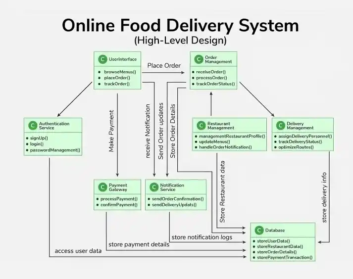
Example of High-Level Design Diagram of an Online Food Delivery System
Below is the HLD diagram for an online food delivery system as demonstrated. The major components include:
- User Interface (Web/Mobile App): Front-end for browsing menus, placing orders, and tracking deliveries; interacts with backend services for requests.
- Authentication Service: Handles user signup, login, authentication, and authorization for secure system access.
- Restaurant Management: Manages restaurant profiles, menus, and handles order alerts and communication.
- Order Management: Core module that processes, validates, and tracks orders while coordinating with restaurants.
- Delivery Management: Manages delivery personnel, tracks delivery status, and ensures timely order delivery.
- Payment Gateway: External service that processes payments, supports multiple methods, and confirms transactions.
- Notification Service: Sends updates via push notifications, email, and SMS for order status and delivery.
- Database: Stores user, restaurant, order, and payment data; supports validation and data retrieval.
Best Practices for Drawing High-Level Design Diagram
Below are some best practices for drawing high-level design diagram:
1. Keep it Simple
An HLD diagram should provide a clear overview of the system architecture without unnecessary complexity.
- Focus on major components and their interactions rather than implementation details.
- Avoid adding too many elements that may make the diagram difficult to understand.
2. Use Standard Notations
Using standard diagram notations ensures consistency and makes diagrams easier for others to understand.
- Use common standards such as UML symbols and architecture icons.
- Maintain consistent symbols and labels throughout the diagram.
3. Iterate
HLD diagrams often evolve as the system design becomes clearer.
- Continuously review and refine the diagram as new requirements or insights appear.
- Update the design to better represent the system architecture.
4. Collaborate
HLD diagrams should be created with input from different stakeholders involved in the project.
- Share the design with team members, architects, and stakeholders for feedback.
- Collaboration helps identify issues early and improves the overall design.
5. Document
Proper documentation ensures that design decisions and architecture are clearly recorded.
- Maintain documentation explaining the system architecture and design choices.
- Keep diagrams updated throughout the project lifecycle for future reference.
Common Mistakes to Avoid While Drawing High-Level Design Diagram
Below are some common mistakes while drawing high-level design diagram:
1. Too Much Detail
Adding too much information to an HLD diagram can make it complex and difficult to understand.
- Focus on major components and their relationships instead of implementation details.
- Keep the diagram simple and leave detailed logic for other design documents.
2. Ignoring Stakeholders
Not involving stakeholders during the design phase can lead to misunderstandings and poor design decisions.
- Include architects, developers, and stakeholders when reviewing the design.
- Their feedback helps ensure the system meets business and technical needs.
3. Lack of Consistency
Using inconsistent symbols or notations can confuse people who read the diagram.
- Follow standard diagram notations such as UML symbols.
- Maintain consistent labels, shapes, and structures throughout the diagram.
4. Neglecting Updates
System architecture may change as the project evolves.
- Regularly update the HLD diagram to reflect the latest system design.
- Keeping diagrams updated ensures accurate documentation for the team.