In this lab, we’ll use Cisco Packet Tracer to create a virtual network environment and observe how data packets travel from one PC to another across different network segments. This hands-on simulation will help you understand the fundamental working of routers, switches, IP configuration, and protocol behavior.
We'll perform:
- Setting up a basic network topology with PCs, switches, and a router
- Configuring IP addresses and routing paths manually
- Using simulation mode to visually trace ARP and ICMP packets
- Testing real-time connectivity using
pingandarp -acommands
Step1: Setting up the topology
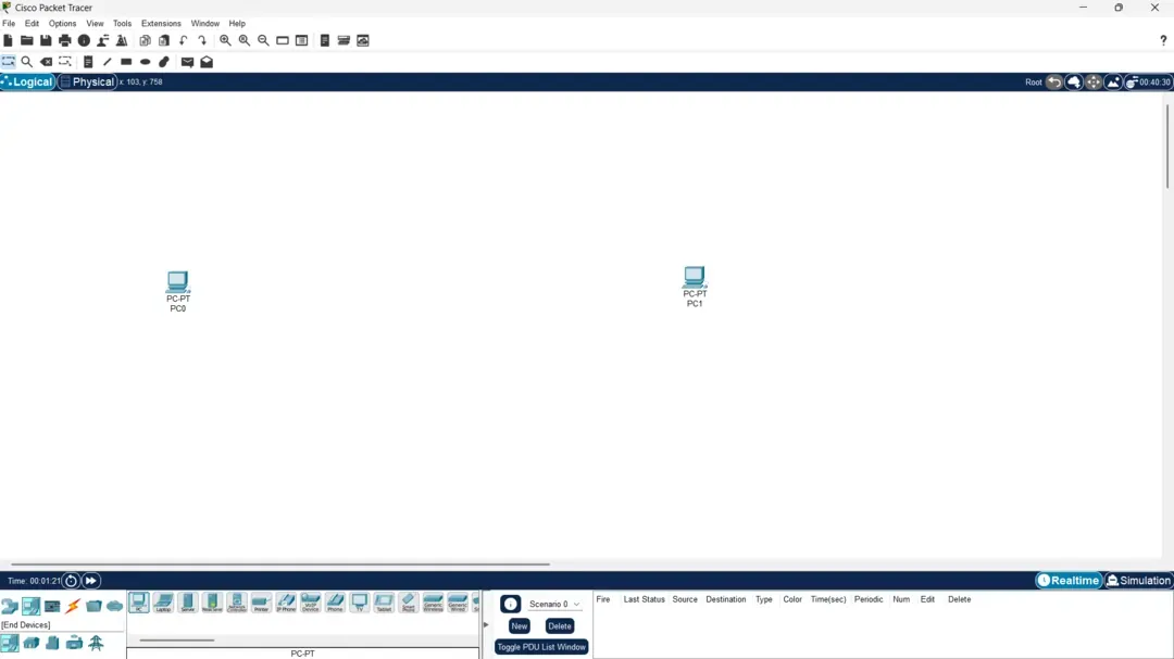
We need to drag 2 PC logo from the End Devices tab at bottom left section, to open it up you can enter this shortcut instead [ Ctrl+ Alt + V ]. Your screen should look like this.
Now we need to add 2 Switches and 1 Router from the Network Devices tab, alternatively [ Ctrl + Alt + R ].
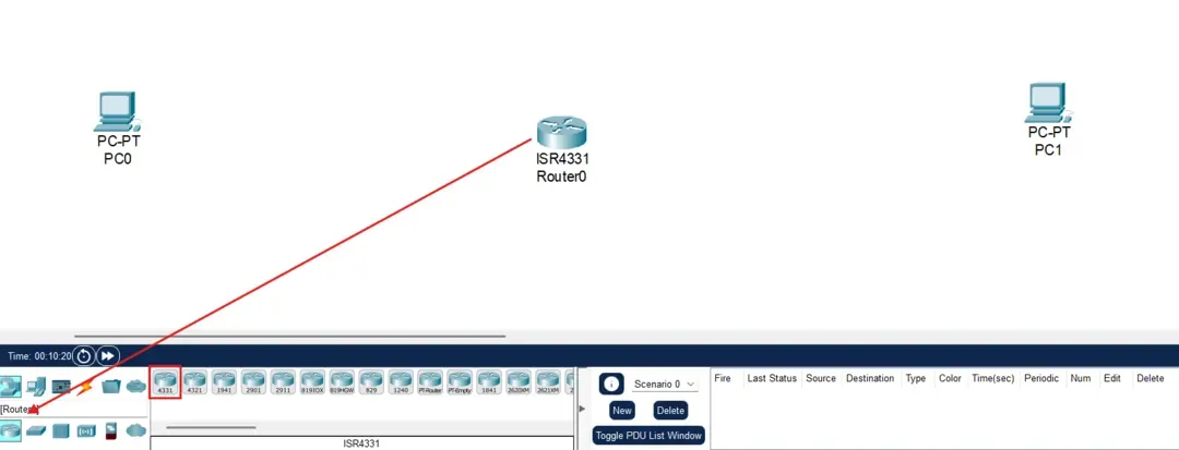
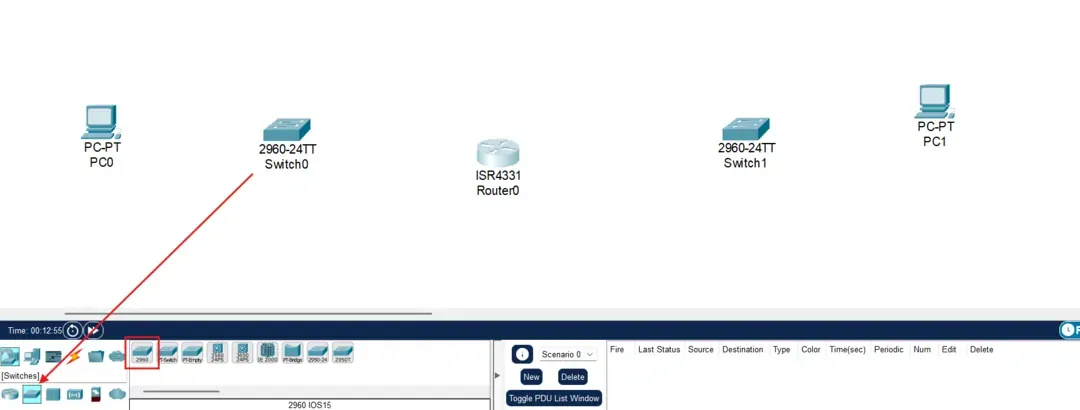
Your screen should look like this as of now.
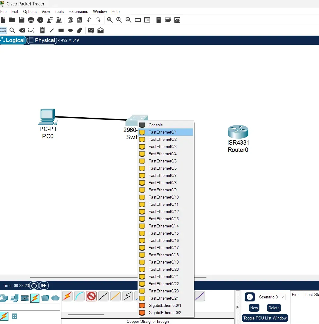
Now adding the connection wire, in this case we will use the copper straight Through wire. Choose the copper wire in the Connection tab, alternatively [ Ctrl + Alt + O ]. When connecting any two devices just like in real life you need to put the wire in the compatible port to make the device work and communicate, Similarly in this we will be choosing FastEthernet0 for PC0.
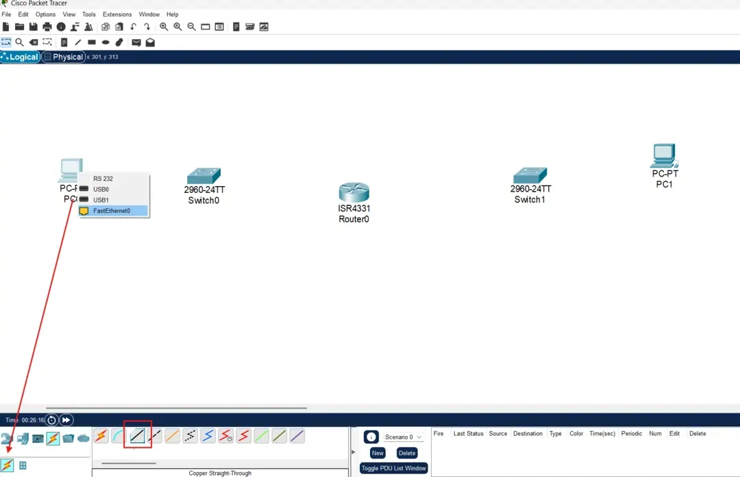
Similarly choose FastEthernet0/1 for the Switch0 when connecting PC0 to the Switch0.
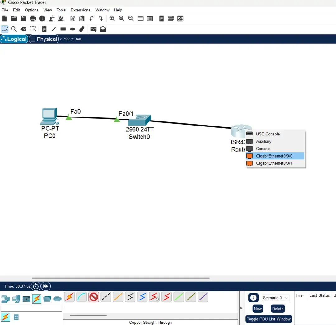
Similarly we need to connect each device in this topology by choosing the appropriate ports. For Swtich0 to Router0 connect through FastEthernet0/2 and Gigabitethernet0/0/0 respectively.
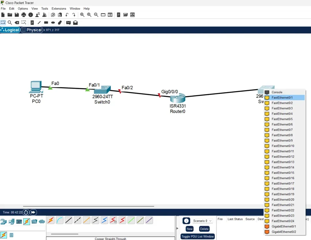
Connecting Router0 using GigabitEthernet0/0/1 to Switch1 using FastEthernet0/2 and then Switch1 to PC1 using FastEthernet0/1 and FastEthernet0 respectively.
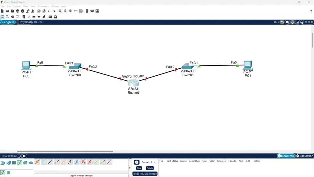
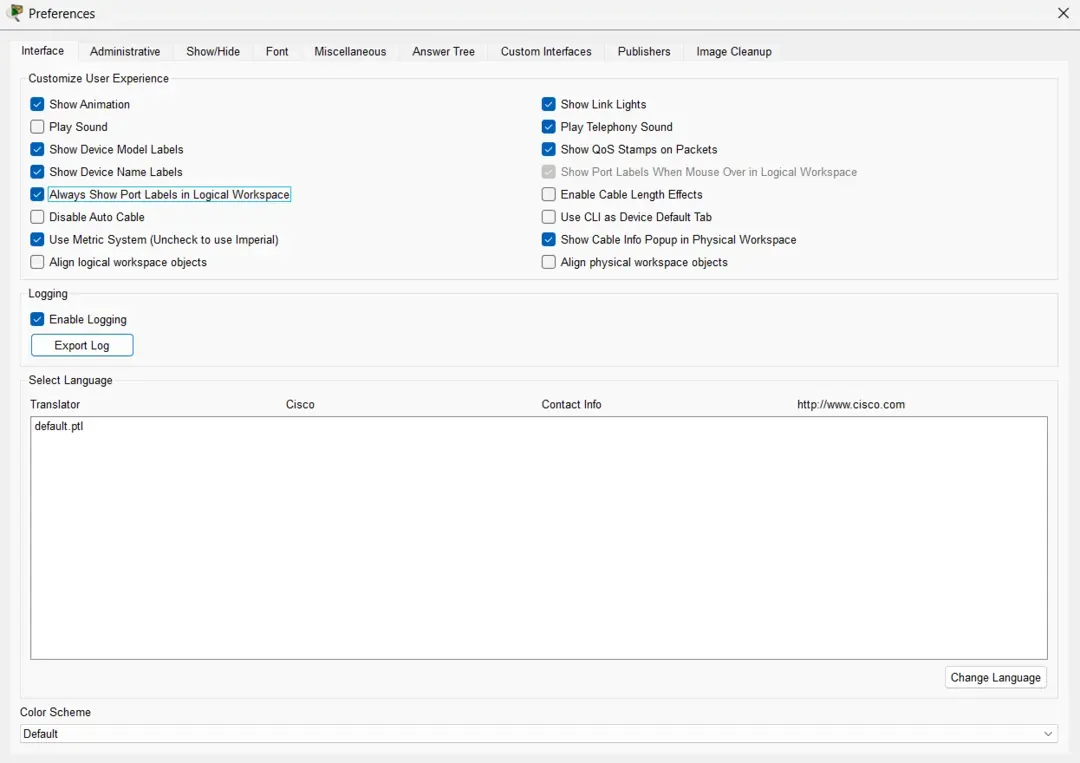
This is what your screen should look finally, apart from the labelling of the ports. If you want the ports to be labelled enable the "Always show port labels in logical workspace" under the preferences section.
Options >> Preferences >> Always show port labels in logical workspace.
Step2: Setting up Network Configuration
PC Configuration:
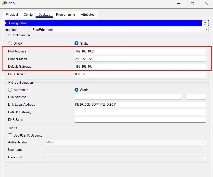
- Click on a PC -> Desktop tab -> IP Configuration
- Set static IP address:
- PC0: IP
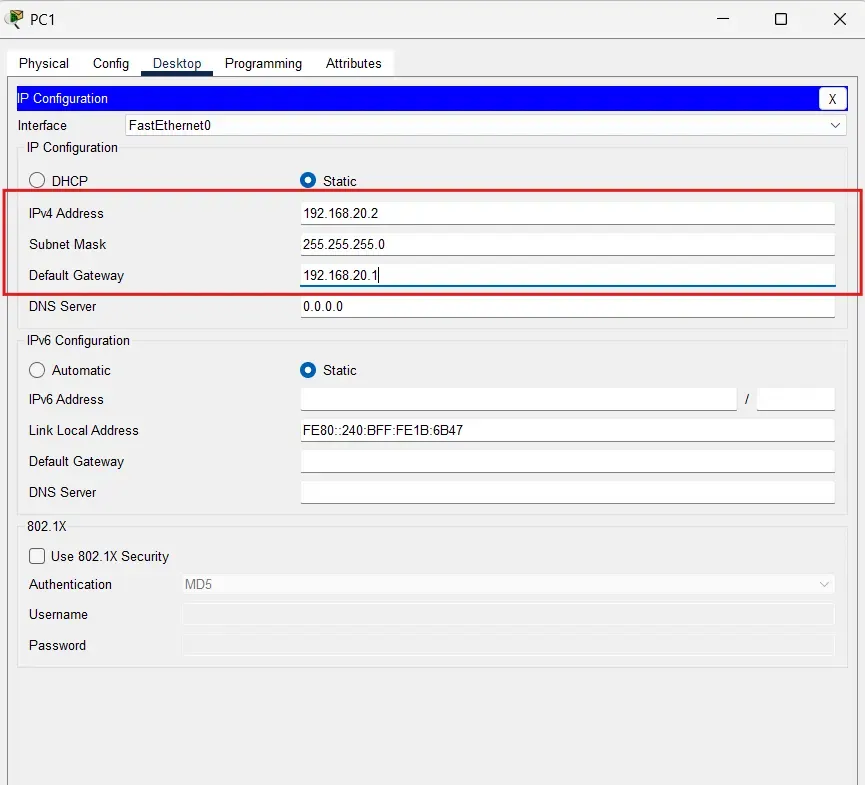
192.168.10.2, Subnet Mask255.255.255.0, Gateway192.168.10.1 - PC1: IP
192.168.20.2, Subnet Mask255.255.255.0, Gateway192.168.20.1
- PC0: IP
Router Configuration:
- Configure the Router
- Click on the Router -> CLI tab
- Press Enter to start, then enter this command:
enable
configure terminal
Configure G0/0 interface (for PC0's network)
interface gigabitethernet0/0
ip address 192.168.10.1 255.255.255.0
no shutdown
exit
Configure G0/1 interface (for PC1's network)
interface gigabitethernet0/1
ip address 192.168.20.1 255.255.255.0
no shutdown
exit
Exit configuration mode
exitSave configuration
write memory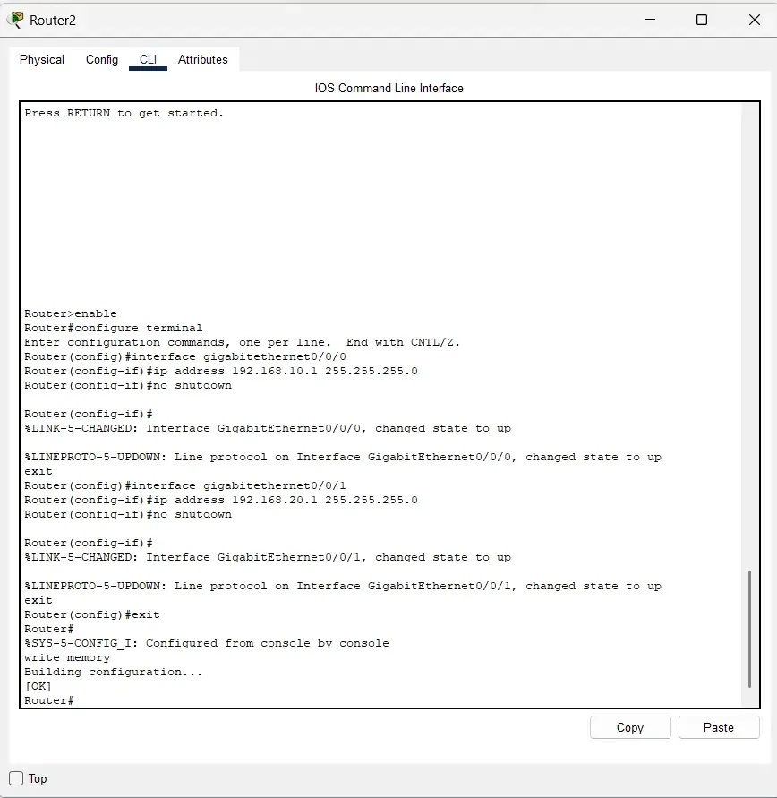
Step 3: Testing Basic Connectivity
- Click on PC0 -> Desktop -> Command Prompt
- Test local gateway:
ping 192.168.10.1- Test remote PC:
ping 192.168.20.2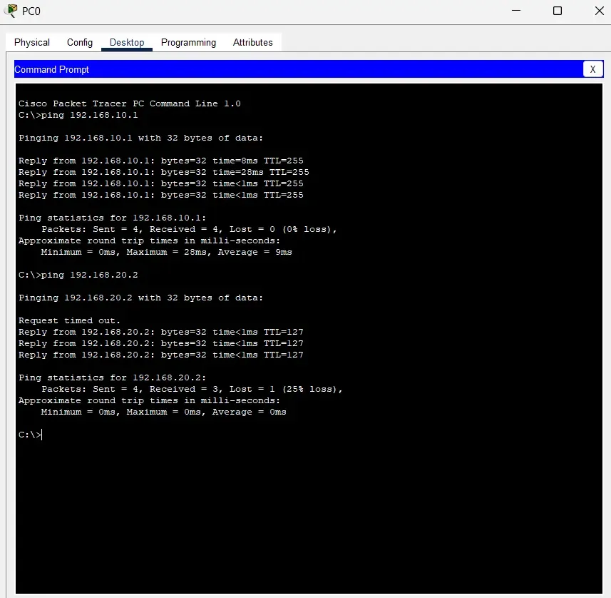
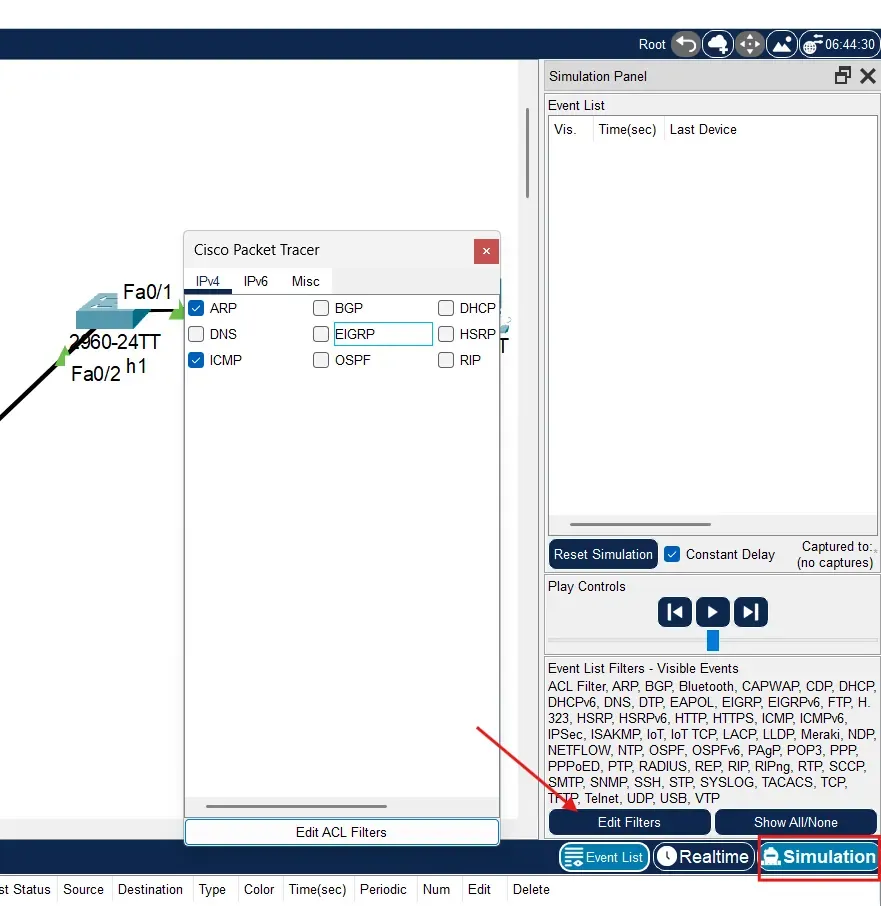
Let's Understand the network functioning in simulation based experience.
On the bottom right corner there would be a button named stimulation click on that button and then click on Edit Filters and uncheck every box in the IPv4 section except ARP and ICMP.
Now, open the command prompt of the PC0 again, and enter these commands:
ping 192.168.10.1Click on the play button to see how the simulation works of the packet sent form one PC to another in real world. You can also click on the packet to get to know more about the layers and how the information is passed on.
Now lets check the arp that will help us give the physical address that has been captured through our previous conversations between the PCs. Enter this command:
arp -a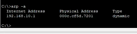
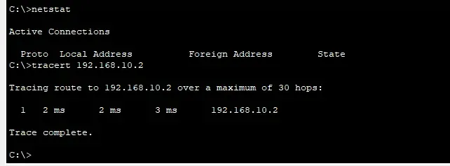
Similarly check the netstat of the PC0, and then you can simulate all the packets send to all the devices in this network like ping request sent to local gateway, remote router interface, remote PC.
Real Life example simulation
Sarah (Accounting) sends data to Mike (Marketing) across different network subnets, showcasing inter-departmental communication through a central router.
Network Topology
- PC0 (Sarah): 192.168.10.2 - Accounting Department
- Router: 10.0.0.1 - Central Hub
- PC1 (Mike): 192.168.20.2 - Marketing Department
Packet Flow Demonstration
- ARP Discovery: PC0 broadcasts "Who has 192.168.20.2?"
- Router Forwarding: Routes ARP request to destination subnet
- ARP Response: PC1 replies with MAC address
- ICMP Communication: Ping/Pong exchange confirms connectivity