A counter is a digital electronic device that counts the number of times an event occurs using a clock signal. With each clock pulse, the count changes, such as in an up counter where the count increases by one. Counters are built using flip-flops and can follow fixed or custom sequences like 0, 1, 3, 2. They can also act as frequency dividers by reducing the input clock frequency. Counters are sequential circuits that count pulses in binary or BCD form and mainly perform counting, timing, and sequencing functions.
Counter Classification
1. Asynchronous Counter
In an asynchronous counter, there is no common (universal) clock for all flip-flops; only the first flip-flop is driven by the main clock, and each subsequent flip-flop is triggered by the output of the previous one, causing the count to ripple through the circuit.
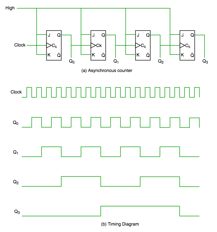
From the timing diagram, Q0 changes immediately at the rising edge of the clock, Q1 changes at the rising edge of Q0, and the same pattern continues for Q2 and Q3. This step-by-step change creates a ripple effect through the flip-flops, which is why it is called a ripple counter or serial counter. A ripple counter is a cascade of flip-flops where the output of one flip-flop acts as the clock input for the next.
2. Synchronous Counter
Unlike an asynchronous counter, a synchronous counter uses a single global clock that drives all flip-flops simultaneously, so all outputs change in parallel. Its main advantage is that it can operate at higher frequencies because it does not suffer from cumulative delay, as the same clock is applied to every flip-flop. Hence, it is also called a parallel counter.
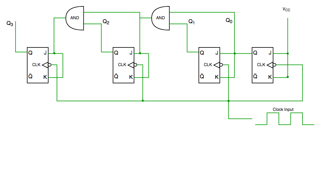
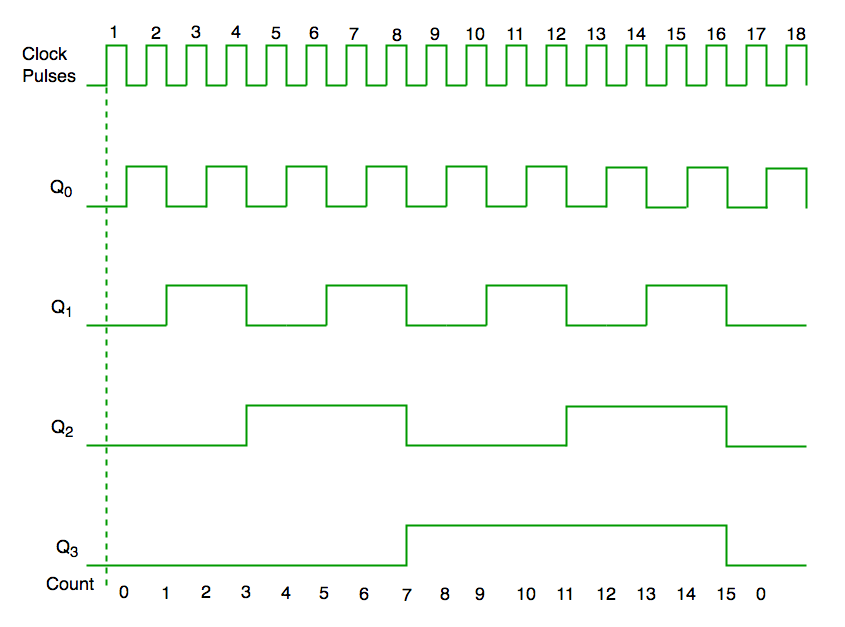
From the circuit diagram, Q0 responds to every falling edge of the clock, Q1 depends on Q0, Q2 depends on both Q1 and Q0, and Q3 depends on Q2, Q1, and Q0, so all flip-flops change state simultaneously under the same clock signal.
Decade Counter
Counts ten states and then resets to its initial state. The most common decade counter counts from 0 to 9, but it can also be designed to count any ten states within 0 to 15 in a 4-bit counter before resetting.
Truth table for simple decade counter:
| Clock pulse | Q3 | Q2 | Q1 | Q0 |
| 0 | 0 | 0 | 0 | 0 |
| 1 | 0 | 0 | 0 | 1 |
| 2 | 0 | 0 | 1 | 0 |
| 3 | 0 | 0 | 1 | 1 |
| 4 | 0 | 1 | 0 | 0 |
| 5 | 0 | 1 | 0 | 1 |
| 6 | 0 | 1 | 1 | 0 |
| 7 | 0 | 1 | 1 | 1 |
| 8 | 1 | 0 | 0 | 0 |
| 9 | 1 | 0 | 0 | 1 |
| 10 | 0 | 0 | 0 | 0 |
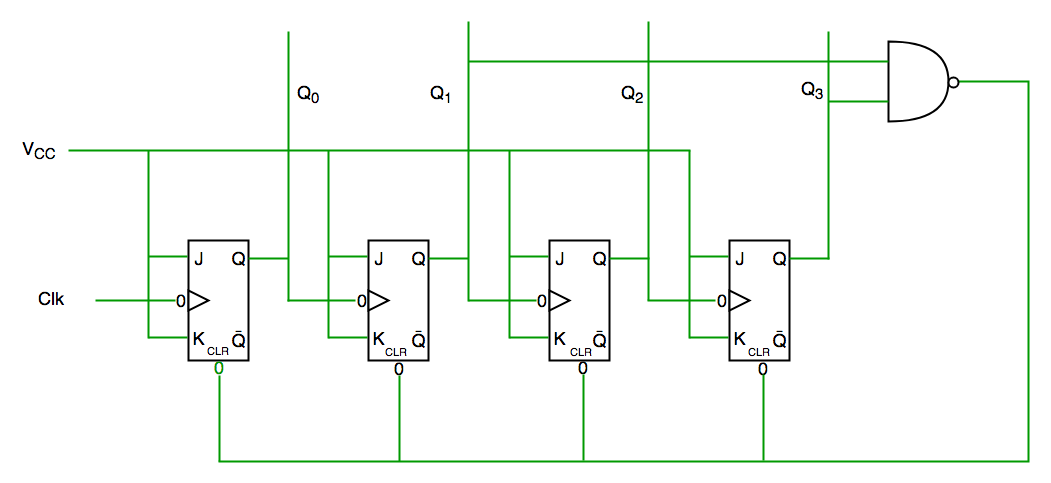
From the circuit diagram, a NAND gate is connected to Q3 and Q1 and its output is fed to the clear input because the binary representation of 10 is 1010. When Q3 and Q1 both become 1, the NAND gate output goes low, activating the clear input, so the counter resets at 10 and starts counting again from 0.
Important point: Number of flip flops used in counter are always greater than equal to (log2 n) where n=number of states in counter.
previous years gate questions
Q1. Consider the partial implementation of a 2-bit counter using T flip-flops following the sequence 0-2-3-1-0, as shown below
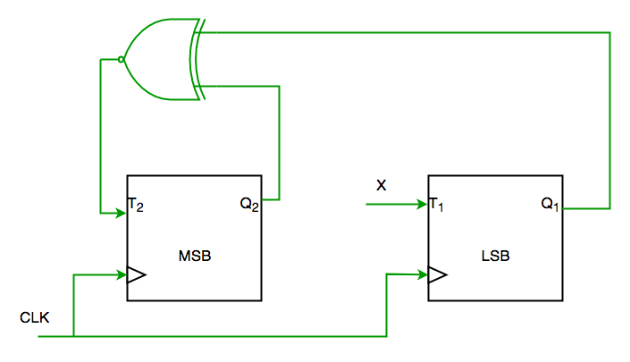
To complete the circuit, the input X should be
(A) Q2?
(B) Q2 + Q1
(C) (Q1 ? Q2)’
(D) Q1 ? Q2 (GATE-CS-2004)
Solution:
From circuit we see
T1=XQ1’+X’Q1—-(1)
AND
T2=(Q2 ? Q1)’—-(2)
AND DESIRED OUTPUT IS 00->10->11->01->00
SO X SHOULD BE Q1Q2’+Q1’Q2 SATISFYING 1 AND 2.
SO ANS IS (D) PART.
Q2. The control signal functions of a 4-bit binary counter are given below (where X is “don’t care”)
The counter is connected as follows:
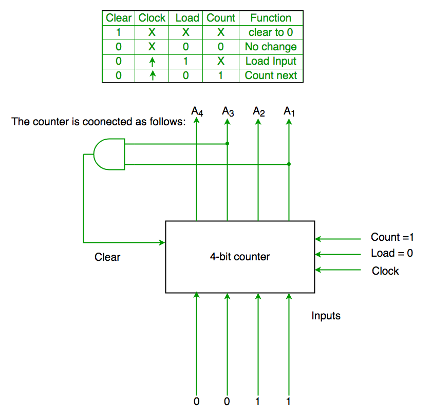
Assume that the counter and gate delays are negligible. If the counter starts at 0, then it cycles through the following sequence:
(A) 0,3,4
(B) 0,3,4,5
(C) 0,1,2,3,4
(D) 0,1,2,3,4,5 (GATE-CS-2007)
Solution:
Initially A1 A2 A3 A4 =0000
Clr=A1 and A3
So when A1 and A3 both are 1 it again goes to 0000
Hence 0000(init.) -> 0001(A1 and A3=0)->0010 (A1 and A3=0) -> 0011(A1 and A3=0) -> 0100 (A1 and A3=1)[ clear condition satisfied] ->0000(init.) so it goes through 0->1->2->3->4
Ans is (C) part.
Quiz on Digital Logic