Getting Started with Atrium
Atrium is a firmware for the ESP family of devices from Espressif. Its concept is to provide one firmware image that can be configured for the specific use case by adding a binary file that provides information about GPIO settings etc.. This short guide shows how to get started with Atrium.
This guide is for people interested in embedded systems that rather want to setup and use their own embedded device, instead of programming themselves in Arduino or so. To follow this guide you should be willing to use a command-line and know how to install packages on Linux. Furthermore, you should be familiar with using a terminal program with a serial connection over an UART.
If you want to follow the steps of this guide with your own hardware, you will need following parts:
- a D1 Mini with 4MB Flash (i.e. not the D1 Mini Lite, look for a board with devices on both of its sides)
- a small breadboard
- a button
- an LED
- a resistor fitting the LED for operation at 5V (e.g. 300 Ohm, depending on the LED)
- a couple of jumper cables
- a micro USB cable
- a computer running Linux (similar steps may be performed on Windows)
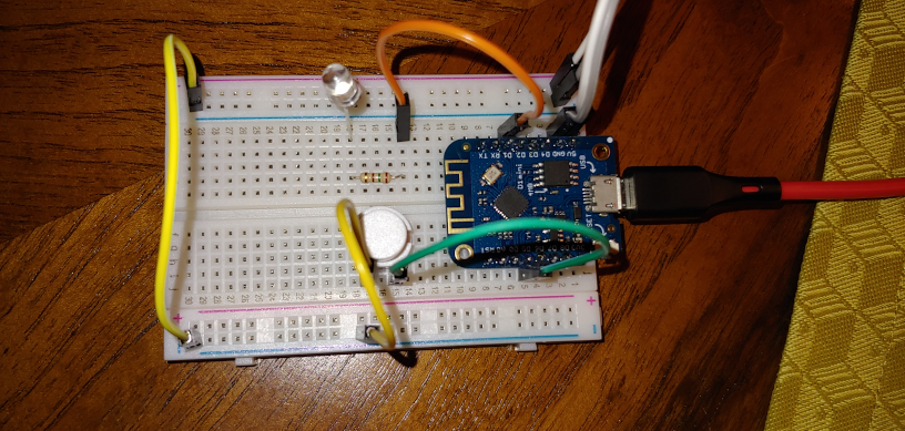
Set the hardware up as shown in the picture below. the LED is driven by 5V and its associated resistor is attached to GPIO5 which is named D1 on the board. The button must be attached to ground and GPIO x which is labeled D5. Finally, attach the board with the USB cable to your laptop.
On Linux you will need following tools: esptool and a terminal program
of your choice that can be operated in raw mode, such as putty, miniterm
or minicom. On Ubuntu simply execute sudo apt install esptool putty
Setup your terminal program with following parameters:
- baudrate: 115200
- uart settings: 8-N-1
- implicit CR on every NL
- enable support for ANSI colors
To program you D1 Mini board, first download the latest Atrium Firmware binary package. Unzip the package and go to the subdirectory for the ESP8266 with 4MB flash. Then perform following steps to prepare your D1 Mini:
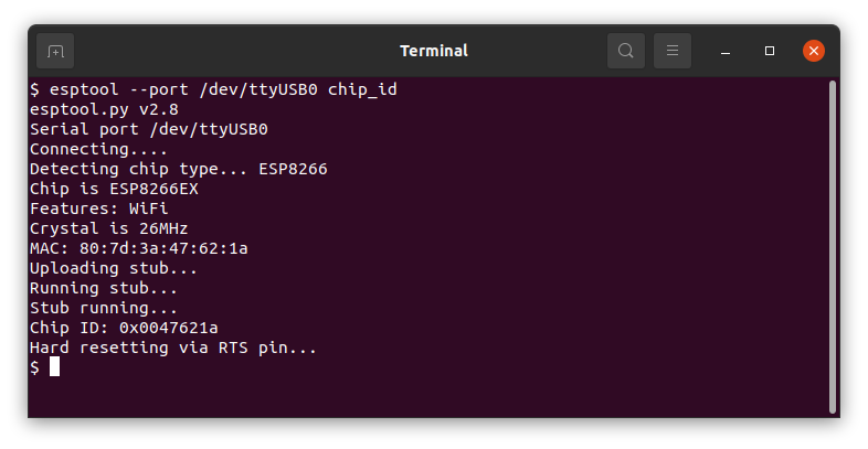
- Identify your D1 Mini on the relevant USB port. Therefore, execute
esptool --port /dev/ttyUSB0 chip_id. This will generate an output as visible below. If you get an error, make sure you use the right character device - i.e. change /dev/ttyUSB0 to /dev/ttyUSB1 etc..
- Erase the device. Be sure to have a backup of its flash, in case you want to restore it after testing Atrium. To erase its flash execute:
esptool --port /dev/ttyUSB0 erase_flash
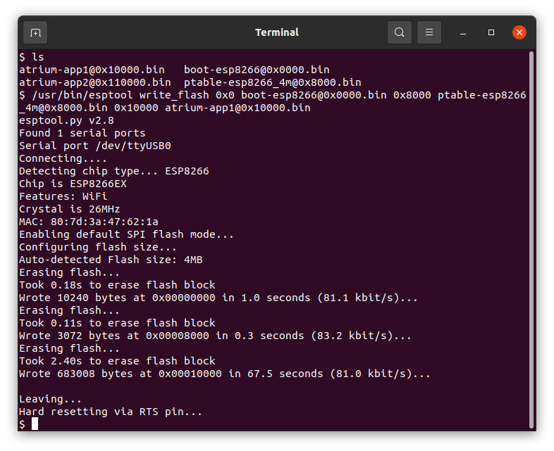
- Flash the firmware image, the partition table, and the bootloader. Therefore execute:
esptool --port /dev/ttyUSB0 write_flash 0x0 boot-esp8266@0x0000.bin 0x8000 ptable-esp8266_4m@0x8000.bin 0x10000 atrium-app1@0x10000.bin
To perform the hardware configuration, you need to connect to the device
with a terminal program for serial connections such as putty or minicom.
This example uses pyserial which must be started with follwoing command:
miniterm.py --raw --eol CR /dev/ttyUSB0 115200
After starting the terminal, you can hit the reset button once, to see the boot process. It terminates without configuration after about 200ms. Booting will state that it was unable to find 'hw.cfg', which is the hardware configuration. On 4MB devices the hardware configuartion can be performed on the device, which is shown in the next steps:
-
(optional) take a peek at the available hardware settings by executing
hwconf show. You can perform also this step after adding the button or LED to see what settings they provide. -
Execute the following lines, to add the button to the configuration and give it a name:
hwconf add button
hwconf set button[0].gpio 14
hwconf set button[0].pull_mode 3
hwconf set button[0].name button@14
These magic words tell Atrium that there is a button at GPIO 14 and that it should be driven with the internal pull-up resistor.
- Next configure the LED.
hwconf add led
hwconf set led[0].gpio 5
hwconf set led[0].name led@5
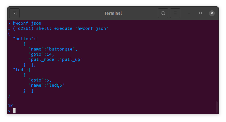
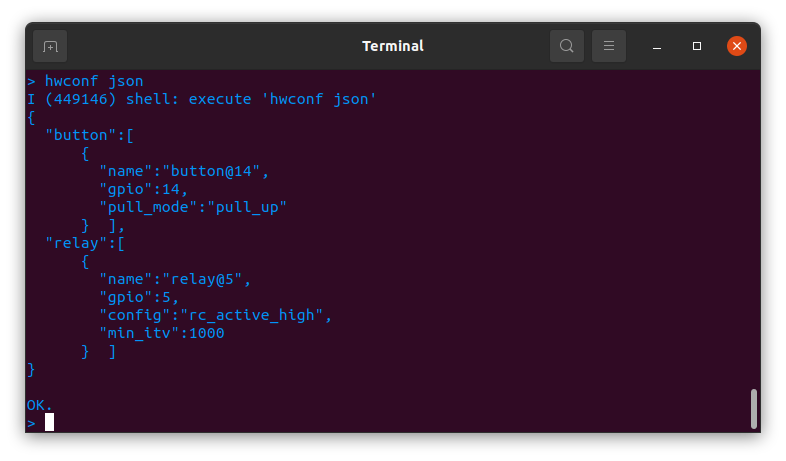
- Check that your configuarion is complete by executing
hwconf json. Compare it with the picture below and save it to NVS (non-volatile storage).
hwconf write
- Perform a minimum setup so that Atrium will not try to run WPS during startup:
nodename myesp
station off
config write
- Now reboot to activate the new hardware configuration:
reboot
Now we have a button and a LED to play with. First let's take a look
what actions and events these devices provice on Atrium. Therefore,
execute event -l and action -l. The output should be a seen below:
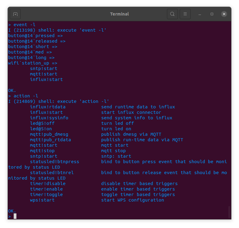
As we can see the button creates events when it gets pressed and released and also creates events when released that tell how long it was pressed (short, medium, long).
To attach the LED to these events execute following commands:
event -a button@14`pressed led@5!on
event -a button@14`released led@5!off
After that the LED will turn on once you press the button and turn off
once you release it. To get debug output of the events execute debug -e event. If you w. If you want to make these actions persistent execute config write.
In this example we want to try something else, so we delete these event action bindings again:
event -d button@14`pressed led@5!on
event -d button@14`released led@5!off
Now we imagine our LED is a relay. So we reconfigure our LED as relay that is active low (config=0) and should adhere to a minimum time-interval for operation of 1000ms:
hwconf clear led[0]
hwconf add relay
hwconf set relay[0].gpio 5
hwconf set relay[0].config 0
hwconf set relay[0].name relay@5
hwconf set relay[0].min_itv 1000
To activate this configuration write it to NVS and reboot:
hwconf write
reboot
Next we attach the button to the relay and setup a timer to make sure the relay does not stay turned on for an infinite time:
event -a button@14`short relay@5!toggle
timer -c relaytimer 60000
event -a relay@5`on relaytimer!start
event -a relaytimer`timeout relay@5!off
So with this configuration, after pressing the button to turn on the "relay", the relay will stay on for 60000ms.
Atrium provides several integrate services that make it interesting to attach to your WiFi. The device operates in stand-alone mode and does not phone home. I simply do not have the interest and infrastructure to track the Atrium devices...
To integrate the Atrium device into your WiFi set the ssid and password of your WiFi for its station mode and the device will query its IP address via DHCP. E.g.:
station ssid mywifi
station pass mydummpassword
station on
config write
To make it more useful configure some basic networking stuff such as DNS
and NTP (use config print to get a list of all options):
config set dns_server 192.168.1.1
config set sntp_server 192.168.1.1
config set timezone -3
Most command have a help page, and you can get a list of available
commands with help -l. To view the help page execute <command> -h or
help <command>.
If you have comments or find a bug, post it on https://www.github.com/maierkomor/atrium.