Search Results for: ""

Showing results for your search

How to Make Your Airbnb WFH Friendly

How to Make Your Airbnb WFH Friendly

One way you can get more Airbnb bookings is if you attract more professionals to your Airbnb by making your rental more work-from-home friendly. In the past couple of years a lot of jobs went and stayed remote. Many people have been taking that opportunity to travel and see different cities and these guest tend to book longer stays which is very desirable. In this post I'll give you some tips and suggest products to make your Airbnb more attractive to guests that are planning to work from home.

I'm going to break down the WFH setup into 3 levels, Basic WFH, Advanced WFH and Video Conferencing WFH and within each of those levels, I'm going to suggest products that fit different budgets from low to high to cover different needs. Keep in mind I'm writing this at the end of 2022 which will affect the prices I mention.

You don't need to spend a lot for a WFH Airbnb setup but I would try to match the budget with the furnishings, area, and guests you are already targeting.
Read More →
Hand Washing On-The-Go Without Sanitizer

Hand Washing On-The-Go Without Sanitizer

In this post I share tips on how I wash my hands away from home without hand sanitizer.

The Corona Virus Pandemic has created a shortage on certain items including hand sanitizer. Even hand soap is difficult to find sometimes. At home I use some foaming hand soap dispensers because they make a significant savings in the amount of soap I use. I use a similar concept when away from home.

Disclaimer

I use this method when I don't have access to running water like if I'm out hiking or camping. Hand sanitizer is good for some things but not great for getting dirt off my hands if I want to clean my hands before eating. I don't have any way to verify how effective this is but it has worked well on dirt and the principles seem sound. With the shortage of hand sanitizer and gloves we need options. This is mine. If this is your only option to wash your hands continue to try to keep your hands away from your face to be safe.

What You'll Need

Step 1: Prepare Soap Solution

If you're using the foaming dispensers follow the instructions. If you're using a spray bottle, I use about a 1 to 4 or 5 ratio of liquid hand soap to water. After mixing I'll test it by spraying it on my hands. I'm looking for a small amount of thin lather. If there isn't enough slipperiness or lather I'll add a little more soap. If my hands get too foamed up I'll add more water.

Step 2: Prepare the Bleach Rinse Solution

I like to add some bleach to the rinse water to help it stay sanitary as well as for it to have some sanitizing effect. Since the FDA recommends a bleach dilution of 50-200 ppm for food contact surfaces including utensils, it seemed like a safe concentration to use on your hands. I wouldn't recommend going above 200ppm but during the ebola virus the CDC put out a document on how to create a bleach hand sanitizing solution that was about 500 ppm bleach.

Try to get bleach that has the concentration of bleach (sodium hypochlorate) listed on the label. If it's not on the label it's at most 3% but I'm not sure if it could be less than that. Use this bleach concentration calculator to help you determine the amount of your bleach you need to add to your bottle. Make a new solution every day. Try not to make too much more than you need. Use the calculator below to determine how much bleach you need.

Bleach Concentration Calculator

Enter the concentration of bleach found on the bottle, the concentration of finished solution you'd like in parts per million (ppm) and the total amount of sanitizer solution you'd like to end up with in ounces.

% bleach concentration
Desired concentration in ppm (50 to 100)
Total volume in ounces
Bleach Needed (use most appropriate measure)
ounces of bleach or
milliliters of bleach or
teaspoons of bleach

Step 3: Spray your hands

Spray your hands or pump out enough foam to start washing your hands. You should have a nice thin lather all over your hands. Rub them strongly together making sure you cover all areas thoroughly. Scrape your nails on your palms, scrub the back of your hands and fingers. Really scrub good.

Step 4: Rinse away soap

If you have access to clean running water use that to rinse your hands. If not use the spray bottle with bleach solution in it. Set the stream to a strong stream and spray the soap off your hands. Aim the spray so it doesn't splash back at you or anyone else.

Step 5: Dry your hands

Let the bleach solution stay on your hands for about a minute to sanitize them. You can let your hands air dry if that's your only choice but it's best to use a clean, dry, paper towel to dry your hands, especially since this method of rinsing isn't as effective as using running water.

How are you washing your hands?

This is what I'm doing. Let me know in the comments what you're doing or if you have any thoughts on my method. What else are you doing to keep safe?
Read More →
Camp Kitchen Equipment

Camp Kitchen Equipment

What equipment I use in my Chuck Box.

I'm very happy with how my chuck box turned out. I designed it mostly around my existing camp cooking gear but I also picked up a few new things that would fit inside and provide me with the comforts of home while out camping. In this post I'll go over the items I use and show in the video and where you can get them.

There are also some things I'd like add. If you're looking for a way to say thanks for the information and the plans you can pick something up from my Chuck Box Amazon Wish List.

Read More →
Plywood Cutting Table Plans

Plywood Cutting Table Plans

Free woodworking plans to build a plywood cutting table that can store away easily yet still support full 4' x 8' sheets of plywood. This will help you get cleaner and more accurate cuts when cutting plywood with a circular saw.

Normally when I'm cutting plywood with a circular saw and either a circular saw guide or my Kreg Rip-Cut jig I just throw some scrap 2x4's on the ground or a sheet of rigid insulation to put the plywood on but lately I've been getting tired of the bending over and being on my knees while cutting sheet goods. I've been using a couple of 2x4's on my saw horses but it doesn't provide as much support for short pieces so I've come up with this alteration that provides more support and doesn't take up a lot of space in my garage when I'm done. I can also pack it up in the back of my truck easily if I need to cut some plywood somewhere else.

What You'll Need

Materials

Tools

  • Circular Saw
  • 2 bar clamps with a minimum 12" opening
  • Combination square or speed square
  • Tape Measure
  • Pencil

Cut Plan

2 of the 2x4's will remain uncut and the entire 8' length. The other 4 will be cut in half to get 8 roughly 4' long pieces mines the saw kerf.

Step 1: Mark and Cut Notches on the Long Boards


Clamp the 2 long boards together with the crown sides up. Mark the center of each notch starting 6" from one end and then every 12".

To mark the actual sides of the notches take one of the short boards and roughly center it over the center line and mark the sides. Or you can measure 3/4" on the side of your center mark.


The placement doesn't need to have laser precision as long as the notches on each board line up and another board can fit in the notch. Lining up shouldn't be a problem since we're going to clamp the boards together and cut out the notches with a circular saw.

Line up the two boards, with their crown side up, and clamp them together. Extend the marks across the tops of both boards and down one 1-3/4" on one face.


Set the depth of your circular saw to the depth of the cut, 1-3/4".


For these cuts I used a speed square to cut out the notch. This is not a time to forget your safety glasses! I made one cut on each line as a reference then started making cuts in between until I had thin enough pieces that I could break off easily.


The bottom will still need to be cleaned up until you get a fairly flat bottomed notch that you can fit a 2x4 on edge in. You can clean it up with a chisel or by carefully using a side to side motion with your circular saw. If you've never done this please find full instructions for the technique before attempting it.


Step 2: Mark Short Notches


Set up the notched long boards in the notches of both of your saw horses. Place one of the short 2x4's in the front pair of notches, and one in the back pair to line up both boards. Try to get the front board as close to centered as you can between the two boards. Then just trace around the area where the long board notch contacts the short board.


Step 2: Cut Notches in Short Boards


Clamp all 8 of the short 2x4's together keeping all the crown sides facing down. Transfer the cut lines you marked in the previous step across the tops of all the boards. 

Set the depth of your circular saw to the depth of your cut (should be around 1-3/4") and start making cuts through all 8 boards simultaneously. Make one cut, move the blade over and make another cut until all the wood from the notch is cleared.

You can use some scrap wood on the sides as stops. The placement of the stops will depend on the dimensions of your circular saw bottom plate. Just line up the blade with one line and place the stop, do the same on the other side. That way you don't have to be too concerned with measuring your saw.


I used my Bora straight edge clamps as guides.

Repeat for the second notch.

Step 4: Assemble Table


Next it's just a matter of putting it all together. 

Set up your saw horses and lay the long boards with the notches facing up in the notches on the saw horses. Don't press them down all the way yet so you can make adjustments.

Place the first short board in one of the end notches and use that to help line up the long boards. Then place a short board on the other end.

Continue placing short boards on the long boards with the short board notches facing down. Make adjustments as you go if necessary.

Once all the boards are in place make sure the long boards are pressed in fully into the notches on the saw horses and that everything is lined up.


When you're done cutting your plywood just reverse the steps to disassemble everything until you need it again.

Step 5: Add Rigid Insulation


This is optional but recommended. Add a 1-1/2" or thicker 4'x8' sheet of rigid insulation over the boards. This will give you more support and help produce cleaner cuts.

When you cut make sure the good side is down. Also, after placing your plywood on the cutting table double check to make sure everything is still stable and hasn't moved before you begin cutting. Practice general good care when using a circular saw.
Read More →
Cost of GreenFiber Vs Atticat Blown In Insulation

Cost of GreenFiber Vs Atticat Blown In Insulation

The recent cold snaps here in the Northeast got me thinking of adding insulation to my walls and attic. Most of it would need to be blown in and there are two options available through the big box stores. GreenFiber Cellulose Insulation and Owens Corning AttiCat Fiberglass insulation. At first glance GreenFiber may seem much cheaper since a package sells for about 1/3rd the price of AttiCat but when you add everything up, AttiCat is actually the cheaper choice. Let's look at why.

First let me say there's a lot of  competing information on which is better, fiberglass or cellulose insulation. Both can be blown into existing walls and attics without significant demolition. The people who mainly sell and install cellulose insulation think it's worlds better than fiberglass and those that manufacture and install fiberglass insulation think that's the best choice. I'm still trying to make up my mind what to believe but both options can be DIY projects and both choices offer a free blower rental with a minimum purchase from Home Depot.

Insulation recommendations changed a few years ago. If your home was built before 1990 there's a good chance you don't have enough attic insulation. If the level of insulation in your attic is at or below the floor joists, you don't have enough. If you can't see your floor joists in the attic because they're covered with insulation you're probably good.

If your home was built before 1980 you may not have any insulation in your walls. If your home was built before 1960 you more than likely don't have insulation in your walls. There's really no way to tell without making a small inspection hole in an exterior wall and visually checking.

To add insulation to existing walls without having to tear down all the drywall the only two affordable choices are blown-in fiberglass or cellulose insulation. Foam is way too expensive for me right now.

Here's what cellulose and fiberglass insulation is currently selling for at Home Depot in my area:

$11.48 for GreenFiber Blown-In Cellulose Insulation
$29.68 for Owens Corning AttiCat Fiberglass Expanding Blown-In Insulation System

When I first saw those numbers I got excited and thought I could blow in cellulose for a lot cheaper than I previously priced fiberglass. Unfortunately you need a lot more cellulose packages than you do fiberglass because the fiberglass is compressed. When it comes to walls it gets even worse which I'll explain after we look at the numbers for attics. Let's say we have a 1,000 sq ft attic we want to insulate by adding an additional R-30 worth of insulation. Here's what the numbers look like.

Attic Insulation Cost Comparison

InsulationPkgs NeededPrice/PkgTotalSavings
GreenFiber R-3044$11.48$505.12
AttiCat R-3016$29.68$474.88$30.24 (5.99%)
OC Fiberglass R-30 Batts29$15.98$463.42$41.70 (8.26%)
GreenFiber R-3859$11.48$677.32
AttiCat R-3820$29.68$593.60$83.72 (12.36%)
GreenFiber R-4981$11.48$929.88
AttiCat R-4926$29.68$771.68$158.20 (17.01%)

The costs above only reflect the cost of the insulation. You get a free 24 hour blower rental if you buy 20 bags of GreenFiber or 10 bags of AttiCat and we're above both of those and I assumed you'd need to rent a truck for either if you don't already have one. Although you're getting a lot more packages of GreenFiber so for some people, that may mean having to rent the HD truck instead of using their own truck.

R-30

If you're only adding an additional R-30's worth of insulation the cheapest option is to use Unfaced R-30 Batts that you just roll over your existing installation (perpendicular to your joists.) if you don't mind crawling around cutting insulation.

If you'd rather blow insulation, AttiCat is slightly less than GreenFiber and not much more than R-30 rolls. Not a big enough difference to choose one over the other if you have a certain preference for either fiberglass or cellulose in my opinion.

R-38 and R-49

If you want to add an additional R-38 worth of insulation or more you really start to see significant savings with AttiCat. For some reason, GreenFiber's recommendations aren't linear. You need proportionally more insulation as you increase R-Value.

At R-30 you need about 2.75 times as many GreenFiber bags as you need AttiCat. At R-38 it's 2.95 times more and at R-49 it's over 3.1 times as many packages.

I think the labor will become an issue as well with cellulose. You have to load, unload, carry and feed about 3 times as many bags of GreenFiber as you do AttiCat.

Wall Insulation Cost Comparison

The following table compares the price for 2,000 square feet of 2x4 framed exterior walls.

InsulationPkgs NeededPrice/PkgTotalSavings
GreenFiber R-1398$11.48$1,125.04
AttiCat R-1327$29.68$801.68$323.68 (28.77%)
AttiCat R-1531$29.68$920.08$204.96 (25.58%)

Things get a lot worse for cellulose insulation when it comes to blowing into existing walls. When installing blown-in insulation in walls you have to blow it in at a higher density than you do for attic installations.

This is true for both cellulose and fiberglass but fiberglass only needs double the amount while cellulose needs triple the amount. With AttiCat you also have the option to add a little more to get a higher R-15 insulation rating. With cellulose you'd probably start busting through your drywall?

Cellulose insulation settles a little bit compared to fiberglass so you really have to pack it in. When you do that, the settling is minimal. I'm guessing that's why it takes much more cellulose insulation compared to fiberglass.

You're saving a lot more money on material cost with fiberglass than with cellulose insulation even if you choose to go with the R-15 installation option of AttiCat. You're also dealing with about 1/3rd as many packages of insulation.

Conclusion

There are pros and cons to each but it's a bit difficult to discern what's truth and what's marketing. For example fiberglass is more affordable and provides good insulation but is itchy. Cellulose is treated with borates which makes it fire retardant and may repel pests and mold. It can be as much as three times heavier than fiberglass which could be an issue in some structures and if not installed to the correct density it can slump over the years leaving an uninsulated void at the top of the wall cavity.

Either GreenFiber or AttiCat is going to be better than not having enough attic insulation or any insulation in your walls if you live in a colder climate. Both can be installed by DIY'ers who spend time reading the instructions and preparing beforehand.

For adding insulation to your attic at R-30 they're similar in cost but as you go deeper you realize more savings with AtticCat.

For adding insulation to existing walls you can save close to 30% with AtticCat versus GreenFiber and you'll need to deal with about 1/3rd as many packages of insulation. They're similar in size but the AtticCat is heavier because it's compressed. Still I think having to open and load that many more packages into the blower is going to get tiring and possibly slow things down.

You can get a free blower rental with either so other costs should be similar.

The numbers I calculated are from current prices in my area. Check to see what GreenFiber
and AttiCat is selling for in your area before you make any decisions.
Read More →
Choosing Daylight or Warm Color Bulbs

Choosing Daylight or Warm Color Bulbs

These days when it comes to energy efficient lighting there are a lot of choices. One of those choices is the color temperature of the light. No longer are we stuck with orange for incandescent, green for fluorescent. Using light bulb color wisely in your home can have positive effects on your and your families lives. Below you'll find my tips for choosing light bulb color.
Read More →
Office Organization: What You Need To Know

Office Organization: What You Need To Know

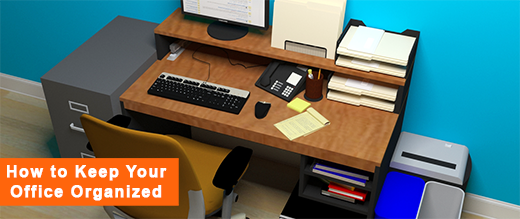
A disorganized office can hurt your productivity and cause you to miss opportunities and waste time. Lots of people tell you what to buy or how to make things look cute. Today I'm going to discuss processes more than products to help keep your work space neat and productive whether it be an office or a home office. How paper should flow through your office, how to create an effective filing system and how to keep files your working on organized plus more.
Read More →
Where to Put Structured Wiring Wall Jacks

Where to Put Structured Wiring Wall Jacks

One of the most difficult tasks in planning a structured wiring project for your home is identifying the location to install your wall jacks. You want to find a location that will minimize the use of long patch cords for safety and aesthetic reasons while still allowing you to move furniture around. Here are some of my tips.

How Many Wall Plates Per Room?

Most rooms should have at least one wall plate that can provide at least a phone line and one network line. Larger rooms such as bedrooms, offices, living rooms, etc should have at least 2.

Step 1: Determine Furniture and Traffic Patterns

In some cases furniture will only fit in a room a certain way, a bed will only work in a bedroom on one particular wall for example. In most cases though there's some flexibility.

What I find works best is to try to identify traffic flow between fixed elements such as doors and windows. These will restrict the locations where you can place furniture. Sketch out your floor plan and mark the major paths people would flow through the room. For this tutorial I just grabbed a floor plan from 2dplan.com and drew arrows indicating the major flows of traffic through the rooms.


Notice how the traffic patterns split the rooms in 2 or 3 sections. Furniture will need to be laid out in a way that doesn't restrict the flow of traffic. The most convenient location for the jacks will be near certain furniture. Since the traffic patterns help guide furniture placement we can also use them to place wall jacks.

In the Master Bedroom for example we have 2 main flows. From the entrance to the window wall and from the window wall to the bath/dresser/porch doors.There are really only 2 ways the bed can be placed in that room. Either on the left wall as shown, or on the top wall. (Okay, 3 if you count in the corner between those two walls but I'm not a big fan of beds in corners.)

Step 2: Put a Wall Plate In Each Traffic Zone

The paths of traffic split up the room into different zones. In Bedroom 1 for example, there's one main traffic path from the entrance door to the patio door that splits the room in half diagonally. The bed is in the top half and the desk is in the lower half but it could easily be set up the other way around.

If we place one wall place on the top wall and one wall plate on the bottom wall we can easily hook up a phone on a nightstand next to the bed, a computer on the desk or a TV opposite the bed in all reasonable furniture placements without having to run wires across the flow of traffic (trip hazard) or without having to run long, unsightly patch cables.

Also consider most rooms will have a sitting/sleeping location, a viewing location (location of TV). The traffic patterns will normally split things up into workable sitting and viewing locations but make sure you can accommodate different sitting/tv locations with your wall plate locations.

Here is how I would run structured wiring and install wall plates in the sample floor plan to get the most functionality and versatility. Each orange dot represents where a wall plate would be installed.


Read More →
RJ11 Phone to RJ45 Jack

RJ11 Phone to RJ45 Jack

Cat5, Cat5e, Cat6 cable is frequently used for wiring telephone jacks. You can send up to 4 telephone lines on one 4 pair cable that terminates at a RJ45 (8P8C) jack. The problem is most phones, even multi-line phones, don't directly plug into an RJ45 jack. We'll discuss some options for connecting phones with RJ11 connectors to an RJ45 port.

Jack Configuration

Before we get into separating the phone lines, lets understand what's going on in the jack. Nobody uses the old quad (green, red, black, yellow) phone cable anymore in new wiring. It's mainly Cat3 or better cable which consists of 4 twisted pairs of wire in blue, orange, green and brown along with their white wire that has a colored stripe (white-blue, white-orange, white-green, white-brown). Since a standard telephone only needs one pair of wires per line, we can send up to 4 lines on each cable. This offers a lot of flexibility and saves time and labor running phone cables in a multi-line system. Even if you're only going to be running a single phone line, you have room for expansion.

For consistency, the ability to utilize all 4 lines and to save space in the wall jack, phone installations are typically terminated in an 8P8C (8 pin 8 conductor) jack. This is the same jack used for your ethernet cable. This is a bigger jack than you might normally expect for a phone which is typically a smaller 6P6C or similar (RJ11, RJ12, etc). 6P6C supports up to 3 lines, 6P4C 2 lines and 6P2C is a single line jack but they all use the same plug. Only difference is the number of wires in the cable.

There are three standard ways of wiring a phone jack. T568A, T568B and USOC. The difference is what colors are connected to what pins on the jack.


T568A is the preferred method for wiring telephone and ethernet jacks and the only method suggested in the residential TIA-570-B specification. Somehow T568B became popular in U.S. commercial installations but T568A is used more outside the U.S. and the Federal Government specifies T568A for their installations. To all the naysayers... See sometimes the government can do things better than the private sector. :) USOC isn't commonly used anymore but is the type of wiring scheme telephones use. 

It would make sense to wire ports following the USOC specification but by using T568A a cable can later be easily switched from voice to data or vice versa in the future. You'll notice that Line 1 and Line 2 on both T568A and USOC are identical. If you have a two line phone, you can plug it directly into a T568A wired jack and both lines will work. The smaller RJ11/12 plugs will fit directly inside an RJ45 jack. It's not preferred since you might damage the other pins but it is designed to work that way.

Unless you need to match a currently installed pinout plan, try to always use T568A. Either way, it's important to know how your jacks are actually wired.

Telephone Jack

Compare the above jacks with old style 2-line phone jacks that used to be used on walls and are still used in phones. They look like this.

The above is a standard 6P4C telephone jack that supports 2 phone lines. Line 1 is on the center pins line 2 is on the next set of outer pins. If twisted pair wiring is used the colors would be white-blue for green, blue for red, white-orange for black and orange for yellow.

If you hook up a single line phone it will only make a connection with pins 2 and 3 (line 1). With a two line phone you'll use all 4 pins.

Connecting Standard 4-Line Phone to RJ45 Jack

The Jack supports 4 lines, the phone supports 4 lines this should be easy right? Nope, not usually. The problem is that most standard 4-line phones don't have a single 4 line RJ45 jack, instead they usually have 2 6P4C (RJ11) jacks that support 2 lines each.

There are a few ways to handle this correctly but let's first talk about how not to do it. You may think that it would make life easy if you just split the pairs of cables behind the wall plate and use 2 RJ11 keystone jacks. This will theoretically work and considering it's just phone there will be minimal issues with interference having a bunch of exposed pairs but it can lead to problems. You will obviously increase the chances of having interference, the wires will be easier to damage, you're going to be taking up extra space in the wall plate and you lose the ability to easily change that port to a network port in the future. It's also prohibited in the spec.

RJ45 4-line to 2 RJ11 2-Line Adapter

There are a number of different splitters (usually named 400E) like this Suttle 400E Cat5 Splitter that plug into the RJ45 Jack and have 2 RJ11 jacks each with 2 lines. These are fairly easy to find but just make sure you're not getting a regular telephone splitter (1 RJ11 to 2 RJ11). It needs to have a male RJ45 on one side and 2 female RJ11's on the other.


Taking a close look at the wiring diagram it appears to follow T568B on the RJ45 side. You can still use it with T568A pinouts but line 2 and 3 will be swapped. If your phone jacks pinouts follow USOC this adapter won't work.

Break Out Cable

If you can't find the splitter above, you can make a breakout cable from twisted pair cable.

On one end you'll crimp an RJ45 jack following the pinout used in your wall jack. On the other you'll crimp 1 or more RJ11 jacks. If you just want to pull one line out for a single phone, pick the pair of wires for the line you want and insert them in the center pins of the RJ11. You can also do 2 2-line RJ11 plugs, 4 1-line RJ11 plugs, whatever works for you.

Break Out Box

Manufacturers of structured wiring systems also have premade break out boxes that will allow you to access the 4 lines in different ways. The Leviton 47609-4x4 4x4 Breakout Module is one example.

 
Since the Leviton systems are geared towards residential installations the Leviton 47609-4x4 is wired according to the T568A pinout unlike the splitter above which is T568B.

DIY RJ45 to RJ11 Break Out Box

If you can't find the break out box above or have special needs you can make your own break out box.

You can make one anyway you'd like but to give you an example let's make a a 4 port box that takes an incoming cable and splits it up to L1&2, L2&1, L3&4, L4&3 similar to the Leviton.

We'll need:
For tools we'll need:
  • Punch down tool with 110 cutting and non cutting blade
  • Modular Plug crimper
  • Screwdriver
We're going to daisy chain 2 pairs on 2 ports for Lines 1 & 2 and then do the same on 2 other ports for lines 3 &4 so we'll have 4 jacks wired like this:


With this configuration we can connect:
  • 4 separate 1-line phones to one RJ45 jack to access all 4 lines.
  • 4 2-line phones 
  • 2 2-line phones
  • or some other variations like one 4-line phone a fax machine and a single line phone.
It's snowing and I don't have any phone jacks handy so I'll be wiring it up using standard 8 wire Cat5e jacks. Same principle but I'm punching down the wires on different pins than I mention in the instructions.

Step 1: Strip cable

Strip the outer jacket of the cable fairly long (maybe 8-10") so you have plenty of wire to work with.


Step 2: L2&1 Jack

We're going to start with one of the center jacks (Lines 2 & 1) and work our way out on either side.  Untwist the orange pair of wires near the base (don't untwist the pair completely) and punch them down to pins 3 & 4 (orange and white-orange) using a non-cutting 110 blade. I'm using the plastic punch down tool that comes with the jacks. Repeat for the blue pair on pins 2 and 5 (white-blue and blue).


Step 3: L1&2 Jack

Next we'll do the Lines 1 & 2 Jack using the same blue and orange pairs except we'll punch them down on the opposite pins as before. 3 and 4 for blue and 2 and 5 for orange. This time when we punch down the wires we'll use the cutting 110 blade to trim off any excess wire.

Have a look at the jack and visualize how you want it to appear in the surface mount box. For me, I'm going to want to punch down the next jack to the right of the first one. Your jacks may be different so stop and check. Remember the pins will be on the top when mounted in the box.

Also, position the next jack far enough away so you have ample wires to position the jacks in the ports on the surface mount box. 


Step 4: L3&4 Jack

Now on the other side of the L2&1 jack we're going to add a jack for Lines 3&4 using the green and brown pairs on pins 3&4 and 2&5 respectively as shown in the previous diagram. 

Use the non-cutting blade and leave enough wire to be able to position the jack in the surface mount box.


Step 5: L4&3 Jack

The last jack is the lines 4 and 3 jack. We'll punch the green pair to pins 2&5 and the brown pair to pins 3&4 using the cutting 110 punch down blade.

Step 6: Insert Jacks In Surface Mount Box

Put the dust covers on the jacks if supplied then install the jacks into the ports on the surface mount box. Mark the surface mount box above the jack so you know it's function (L1&2, L2&1, L3&4, L4&3 or whichever configuration you chose.)

Step 7: Crimp RJ45 Connector

On the other end of the of the wire crimp on an RJ45 connector using the appropriate pinout for your wall jack. Either T568A, T568B or USOC.
Read More →
Deciphering A Structured Wiring System

Deciphering A Structured Wiring System

If you purchase a newer home (or office) that already has structured wiring installed it's important to figure out how it works and where all those wires go. In this article I'll provide some tips to do just that.
I recently received an email from Jon who is trying to make the best use of one of these structured wiring panels but is having a hard time figuring how it's all connected. Jon writes:
Hi Tom,
We recently moved into our home that was built in 2000. It has a patch panel in the mechanical room/closet and we're trying to decipher what's going on here. I've made an album on imgur and described everything and I was hoping you could just let me know if I'm on the right track with my current thinking.
http://imgur.com/a/7Xrxa
Thank-you so much!
Jon
Jon included a lot of pictures of his setup. Unfortunately it's very difficult to figure out what's going on without actually being there. There are some standard ways of doing things for some aspects but not all and some installers will do things their own way, sometimes the wrong way.

I can provide some tips however on how Jon can help figure things out himself with a bit of work. These tips will also help you even if you have a different brand of structured wiring cabinet.

Step 1: Review Labels/Documentation 

If you're lucky someone will have left some sort of documentation. It may be a simple map showing where the wires go or something more complex. Even if it's just a set of labels on the different ports that may be just enough to help you get going.

If you live in a development, you can check with management to see if they have any documentation. If you know the builder you may be able to content them.

Unfortunately for Jon the panel wasn't labeled and even though the individual cables were labeled, it was just a numerical code that he can't decipher.

Step 2: Identify the Manufacturer

In these types of residential systems it's common that all the components are from one manufacturer. Knowing this can help you see what types of standards they have and know what other components you can add in the future.

This is Jon's Structured Media Panel.


It appears to be a Honeywell FutureSmart SuperPro panel. Not sure if these systems are still made as there are a lot of broken links on Honeywell's site in reference to these systems but I did find this Honeywell FutureSmart Brochure that lists various components. I recommend downloading that in case it disappears too.

The top part of these panels deal with wiring that goes to the jacks and the bottom portion is where special modules are used to deal with incoming voice, data and video lines and distribution. 

On the top, each horizontal line of connections is one zone. A zone can be a single room or a single wall plate in that room.

Step 5: Identify Jacket Color Conventions

These panels are wired with coaxial, category (twisted pair) and sometimes fiber cables. The type of cable used helps identify what it's for. Coax for video, fiber and category cable for networking/phone.

Category cable comes in different grades, Cat3, Cat5, Cat5e, Cat6, etc. If you have Cat3 and another such as Cat5, it's likely the Cat3 cables are used for phone. Most installers though will just use the same type of cable (Cat5/5e/6) for both phone and data. In these cases some will have their own color coding conventions to help identify the purpose of the cable. For example blue may be for data and white for voice. Some other cables such as incoming lines may also have different colors.

As I mentioned, there are no standards but many installers do stick with their own conventions. If you can identify what conventions they use, it can help speed things up.

Step 4: Trace Wires Between Panel and Jacks

The first step is to figure out how all the jacks are wired to the patch panel. This is the backbone of the wiring system. Wires will run between the wall jacks and eventually be punched down to the back of the panel. This is more or less 'fixed' wiring. It's just a way to bring the jack connections down to a central location, the panel.

In the SuperPro panel Jon has, all the jacks will be punched down in the back of the top portion of the patch panel. I'm not very familiar with these panels but my understanding is each row of ports is a zone (room) and there are two sides (Interactive A and B) which can be used to distinguish between two wall plates in the room. All the ports on the left will be for Wall plate A and right will be for Wall plate B in each room. Looks like Jon's installation may be following this convention based on the types of ports used on each side.

There are a number of ways to do this but the fastest and easiest way to do this is to pick up a Klein Tools VDV501-809 VDV Scout Pro Tester Kit.


In addition to testing cable, it comes with a number of remotes for RJ45 and F type jacks. You insert these remotes into the jacks upstairs, then you go down to the panel and figure out which ports in the panel map to the jacks that have remotes in them. This is an older model that has only 5 remotes for each type of port. It's a pretty good value. If you want the newer version which also has more remotes check out the Klein Tools VDV501-825 VDV Scout Pro 2 LT Tester and Remote Kit.

In Jon's case, since the wires were labeled at the panel, it's possible they are also labeled behind the jacks. Popping off the wall plate cover and inspecting the wires might reveal labels that make it easy to figure out where those jacks are terminated on the panel. There are two concerns with doing it this way. It's possible the labels fell off or were mislabeled but more importantly it prevents you from buying a new toy. :)

Step 5: Identify Incoming Service Lines

All incoming lines should be terminated in this panel. That's the hole point of having a panel like this. Doesn't look like that's the case for Jon though as the video installers may have terminated their lines somewhere else.

You can use the Klein Scout to help identify these as well but hopefully these are a little more obvious. The Klein Scout has a tone generator and together with the Klein VDV500-060 PROBEplus Tone Tracing Probe you can trace the lines.

In the FutureSmart SmartPro system that Jon is using, the incoming lines should be terminated at the bottom of the panel where the distribution modules are.

Step 6: Identify Patch Cords

At this point we should know where all the jacks come in on the panel and where all the incoming service lines are connected. The way the incoming signals are distributed to the various jacks is by use of patch cords between the top zone ports and the bottom distribution ports. Let's look at the picture of the panel again.


That's the top portion of the panel. It shows the patch cords connected to the ports that lead to the in-room jacks.

And here's the bottom portion of the panel that has the distribution modules.


The patch cords we see here should be the other end of the patch cords in the first photo. Remember, fixed lines are generally punched down in the back and then patch cables are usually used in the front to connect fixed wiring to services.

If you want to send a video signal to zone 1 wall plate B for example you'd add a patch cable between an output jack in the Coax Distribution HUB and the port on the right of the first row of the top of the panel. Same for data and phone using their respective distribution modules.

In this Honeywell system you can connect multiple inputs to distribute them over the same wires as long as those signals don't overlap. For example you can have a CableTV input as well as input from something like an over-the-air TV antenna or the output of a DVD player together. Satellite however doesn't tend to play well on the same cable as other feeds. The Honeywell Coax Distribution HUB Jon is using is also amplified. Signals lose their strength over long runs and many splits so the amplifier boosts the signal to ensure the signal at each port is strong enough.

Next the voice jacks need to be patched into the incoming voice services somehow. This can be done in a number of ways (patch panels, 110 blocks, 66 blocks, etc.) In Jon's case it looks like the module underneath the Coax HUB does just that. Looks like a 4-line telephone distribution module which can distribute up to 4 incoming lines on each cable.

There are also some 2 line distribution modules but it does not appear that they are used.

Finally, the data jacks need to be patched into the network. Unlike video and voice that can just be tied together, networking requires a network switch to deliver the best performance to the network. This is a smart device that routes network traffic to the specific port that the traffic is addressed to.

I haven't seen a networking switch in any of Jon's photos but I assume it must be there somewhere.  Either a Honeywell Switch Module or an external network switch mounted outside the panel. Patch cables will need to be used to connect the jacks (top part of panel) to the ports on the switch. One switch port for each RJ45 jack that you want to enable for data. Also connected to the network switch will need to be the incoming internet connection.

Label and Document Everything

All long the way you should document everything you find. Create maps, Label wires and patch panels. Before you do though, stop and come up with a good naming convention.

In my post on Organizing Cable Clutter I mentioned I use the Brother Easy Handheld Label Maker (PTH100). I chose it because not only can it create labels that you can use for marking patch panels but you can also use it for creating cable flags.


If you're a professional installer there are better choices that really save time and create nicer cable labels but they also cost a lot of money. The Brother costs about $20. You might need to trim some of the labels to get them to fit nicely on patch panels but it's much better than trying to read my chicken scratch.

Summary

While we were looking at a specific brand of structured media panel here, you can use the advice above for most structured wiring installations as they follow similar conventions.

Room Jacks are terminated to the back of a patch panel.

Incoming lines are also terminated in some fashion to a patch panel or a distribution device.

Patch cords are used to connect jacks to incoming services.

Once you break it down to those 3 types of cables it becomes a little easier to understand.
Read More →